P0048 - TURBOCHARGER BOOST CONTROL CIRCUIT HIGH
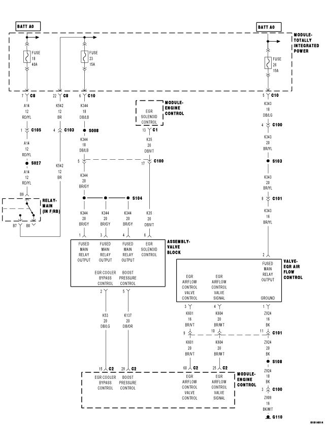
For a complete wiring diagram Refer to Section 8W
- When Monitored:
With the ignition on and the Boost Pressure command on.
- Set Condition:
The ECM detects that the (K137) Boost Pressure Control circuit is shorted to voltage for 2.0 seconds.
| Possible Causes |
| INTERMITTENT DTC |
| (K137) BOOST PRESSURE CONTROL CIRCUIT SHORTED TO VOLTAGE |
| (K137) BOOST PRESSURE CONTROL CIRCUIT OPEN OR HIGH RESISTANCE |
| VALVE BLOCK ASSEMBLY |
| ENGINE CONTROL MODULE (ECM) |
Always perform the Pre-Diagnostic Troubleshooting procedure before proceeding. (Refer to 9 - ENGINE - DIAGNOSIS AND TESTING)
Diagnostic Test
1. DTC IS ACTIVEIgnition on, engine not running.
With the scan tool, clear DTCs in the Engine Control Module (ECM).
With the scan tool, actuate the Boost Pressure at 100%.
Monitor the scan tool for at least two minutes.
With the scan tool, select View DTCs.
Is the status Active for this DTC?
Yes
- Go To 2
No
- Refer to the *CHECKING FOR AN INTERMITTENT DTC Diagnostic Procedure. (Refer to 9 - ENGINE - DIAGNOSIS AND TESTING)
2. (K137) BOOST PRESSURE CONTROL CIRCUIT SHORTED TO VOLTAGE
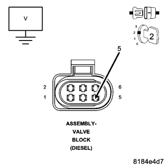
Turn the ignition off.
Disconnect the Valve Block Assembly harness connector.
Disconnect the Engine Control Module (ECM) harness connector.
Remove the Main Relay.
Connect a jumper wire between cavity B7 and cavity B9 of the Main Relay Connector.
Turn the ignition on.
Measure the voltage of the (K137) Boost Pressure Control circuit in the Valve Block Assembly harness connector.
Is there any voltage present?
Yes
- Repair the (K137) Boost Pressure Control circuit for a short to voltage.
- Perform the ECM Verification Test Ver. 1. (Refer to 9 - ENGINE - DIAGNOSIS AND TESTING)
No
- Go to 3
3. (K137) BOOST PRESSURE CONTROL OPEN OR HIGH RESISTANCE
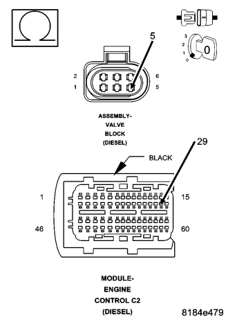
Turn the ignition off.
Measure the resistance of the (K137) Boost Pressure Control circuit between the Valve Block Assembly harness connector and the Engine Control Module (ECM) harness connector.
Is the resistance below 10.0 ohms?
Yes
- Go to 4
No
- Repair the (K137) Boost Pressure Control circuit for an open circuit or high resistance.
- Perform the ECM Verification Test Ver. 1. (Refer to 9 - ENGINE - DIAGNOSIS AND TESTING)
4. VALVE BLOCK ASSEMBLY
Connect the Engine Control Module (ECM) harness connector.
Turn the ignition on.
With the scan tool, actuate the Boost Pressure (Boost Pressure Actuator) to 100%.
Using a 12 volt test light connected to 12 volts, check the (K137) Boost Pressure Control circuit in the Valve Block Assembly harness connector.
NOTE: The test light should be illuminated and bright. Compare the brightness to that of a direct connection to the battery.
NOTE: The circuit will remain actuated by the controller for 30 seconds. Be certain the actuation is active when checking the circuit.
Is the test light illuminated and bright with the actuation at 100%?
Yes
- Replace the Valve Block Assembly in accordance with the Service Information.
- Perform the ECM Verification Test Ver. 1. (Refer to 9 - ENGINE - DIAGNOSIS AND TESTING)
No
- Go to 5
5. ENGINE CONTROL MODULE (ECM)
Using the wiring diagram/schematic as a guide, inspect the wiring and connectors between the Valve Block Assembly and the Engine Control Module (ECM).
Look for any chafed, pierced, pinched, or partially broken wires.
Look for broken, bent, pushed out or corroded terminals.
Refer to any Technical Service Bulletins that may apply.
Were any problems found?
Yes
- Repair as necessary.
- Perform the ECM Verification Test Ver. 1. (Refer to 9 - ENGINE - DIAGNOSIS AND TESTING)
No
- Replace the Engine Control Module (ECM) in accordance with the Service Information.
- Perform the ECM Verification Test Ver. 1. (Refer to 9 - ENGINE - DIAGNOSIS AND TESTING)