P0339-CRANKSHAFT POSITION SENSOR INTERMITTENT
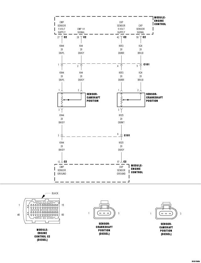
For a complete wiring diagram Refer to Section 8W
- When Monitored:
With the engine cranking or running. Engine speed above 50 rpm. No Sensor Supply DTC's present.
- Set Condition:
The Engine Control Module (ECM) does not receive a signal from the Crankshaft Position Sensor when the Camshaft Position Sensor indicates engine rpm.
| Possible Causes |
| (K853) CKP SENSOR 5-VOLT SUPPLY CIRCUIT OPEN |
| (K24) CRANKSHAFT POSITION SENSOR SIGNAL CIRCUIT SHORTED TO VOLTAGE |
| CHECKING (K853) CKP SENSOR 5-VOLT SUPPLY CIRCUIT |
| DAMAGED CKP SENSOR OR CRANKSHAFT |
| ECM |
| (K925) CKP SENSOR GROUND CIRCUIT OPEN |
| INTERMITTENT CONDITION |
| (K24) CKP SENSOR SIGNAL CIRCUIT OPEN |
| (K853) CKP SENSOR 5-VOLT SUPPLY CIRCUIT SHORTED TO GROUND |
| (K24) CKP SENSOR SIGNAL CIRCUIT SHORTED TO GROUND |
| CRANKSHAFT POSITION SENSOR |
| (K853) CKP SENSOR 5-VOLT SUPPLY CIRCUIT SHORTED TO THE (K925) CKP SENSOR GROUND CIRCUIT |
| (K24) CKP SENSOR SIGNAL CIRCUIT SHORTED TO THE (K925) CKP SENSOR GROUND CIRCUIT |
Always perform the Pre-Diagnostic Troubleshooting procedure before proceeding. (Refer to 9 - ENGINE - DIAGNOSIS AND TESTING)
Diagnostic Test
1. VERIFY ACTIVE DTCNOTE: If DTC P0652 or P0653 is present with this DTC, diagnose DTCs P0652 or P0653 before diagnosing this DTC.
NOTE: The Timing Belt/Chain must be correctly installed and operational before diagnosis can be made. Refer to the Service Information to ensure the timing belt is properly installed.
NOTE: If the ECM detects and stores a DTC, the ECM also stores the engine/vehicle operating conditions under which the DTC was set. Some of these conditions are displayed on the scan tool at the same time the DTC is displayed.
NOTE: Before erasing stored DTCs, record these conditions. Attempting to duplicate these conditions may assist when checking for an active DTC.
Turn the ignition on.
With the scan tool, erase the ECM DTCs.
Attempt to start the engine cranking the engine for at least 7 seconds.
With the scan tool, read the ECM DTCs.
Does the scan tool display this DTC?
Yes
- Go To 3
No
- Go To 2
2. TEST DRIVE
With the scan tool, erase the ECM DTCs.
Test drive the vehicle.
With the scan tool, read the ECM DTCs.
Does the scan tool display this DTC?
Yes
- Go To 3
No
- Refer to the *CHECKING FOR AN INTERMITTENT DTC Diagnostic Procedure. (Refer to 9 - ENGINE - DIAGNOSIS AND TESTING)
3. CHECKING (K24) CRANKSHAFT POSITION SENSOR SIGNAL CIRCUIT
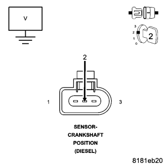
Turn the ignition off.
Disconnect the Crankshaft Position Sensor harness connector.
Turn the ignition on.
Measure the voltage of the (K24) CKP Sensor Signal circuit at the CKP Sensor harness connector.
Select the appropriate voltage reading.
Voltage is above 5.4 volts.
- Go To 4
Voltage is between 4.7 and 5.4 volts.
- Go To 5
Voltage is below 4.7 volts.
- Go To 12
4. (K24) CRANKSHAFT POSITION SENSOR SIGNAL CIRCUIT SHORT TO VOLTAGE
Turn the ignition off.
Disconnect the ECM harness connectors.
Remove the Main Relay.
Connect a jumper wire between cavity B7 and cavity B9 of the Main Relay connector.
Turn the ignition on.
Measure the voltage of the (K24) CKP Position Sensor Signal circuit at the CKP Sensor harness connector.
Is the voltage below 1.0 volt?
Yes
- Replace and program the Engine Control Module in accordance with the Service Information.
- Perform the ECM Verification Test Ver. 1. (Refer to 9 - ENGINE - DIAGNOSIS AND TESTING)
No
- Repair the (K24) Crankshaft Position Sensor Signal circuit for a short to voltage.
- Perform the ECM Verification Test Ver. 1. (Refer to 9 - ENGINE - DIAGNOSIS AND TESTING)
5. CHECKING (K853) CRANKSHAFT POSITION SENSOR 5-VOLT SUPPLY CIRCUIT
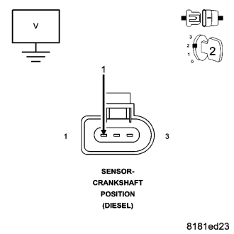
Measure the voltage of the (K853) CKP Sensor 5-Volt Supply circuit at the CKP Sensor harness connector.
Select the appropriate voltage reading.
Voltage is above 5.4 volts.
- Repair the (K853) CKP 5-Volt Supply circuit for a short to voltage.
- Perform the ECM Verification Test Ver. 1. (Refer to 9 - ENGINE - DIAGNOSIS AND TESTING)
Voltage is between 4.7 and 5.4 volts.
- Go To 6
Voltage is below 4.7 volts.
- Go To 9
6. (K925) CRANKSHAFT POSITION SENSOR GROUND CIRCUIT OPEN
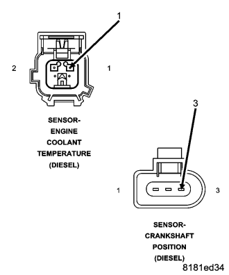
Turn the ignition off.
Disconnect the ECT Sensor harness connector.
Connect one end of a jumper wire to the (K2) ECT Sensor signal circuit in the ECT Sensor harness connector.
Connect the other end of the jumper wire to the (K925) CKP Sensor Ground circuit in the Crankshaft Position Sensor harness connector.
Turn the ignition on.
With the scan tool in Engine, Sensors, read the Engine Coolant Temp volts.
Is the voltage below 0.5 volt?
Yes
- Go To 8
No
- Go To 7
7. (K925) CRANKSHAFT POSITION SENSOR GROUND CIRCUIT OPEN
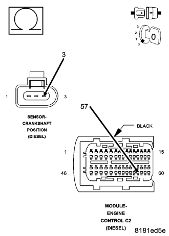
Turn the ignition off.
Measure the resistance of the (K925) CKP Sensor Ground circuit between the CKP Sensor harness connector and the ECM harness connector.
Is the resistance below 10.0 ohms?
Yes
- Replace and program the ECM in accordance with the Service Information.
- Perform the ECM Verification Test Ver. 1. (Refer to 9 - ENGINE - DIAGNOSIS AND TESTING)
No
- Repair the (K925) CKP Sensor Ground circuit for an open.
- Perform the ECM Verification Test Ver. 1. (Refer to 9 - ENGINE - DIAGNOSIS AND TESTING)
8. DAMAGED CRANKSHAFT POSITION SENSOR OR CRANKSHAFT
Turn the ignition off.
Remove the CKP Sensor.
Inspect the CKP Sensor for conditions such as loose mounting screws, damage, or cracks.
Inspect the Crankshaft for conditions such as damage, debris or cracked teeth.
Is there any evidence of these conditions?
Yes
- Repair as necessary.
- Perform the ECM Verification Test Ver. 1. (Refer to 9 - ENGINE - DIAGNOSIS AND TESTING)
No
- Replace the Crankshaft Position Sensor in accordance with the Service Information.
- Perform the ECM Verification Test Ver. 1. (Refer to 9 - ENGINE - DIAGNOSIS AND TESTING)
9. (K853) CRANKSHAFT POSITION SENSOR 5-VOLT SUPPLY CIRCUIT OPEN
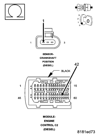
Turn the ignition off.
Measure the resistance of the (K853) CKP Sensor 5-Volt Supply circuit between the ECM harness connector and the CKP Sensor harness connector.
Is the resistance below 10.0 ohms?
Yes
- Go To 10
No
- Repair the (K853) CKP Sensor 5-Volt Supply circuit for an open.
- Perform the ECM Verification Test Ver. 1. (Refer to 9 - ENGINE - DIAGNOSIS AND TESTING)
10. (K853) CRANKSHAFT POSITION SENSOR 5-VOLT SUPPLY CIRCUIT SHORTED TO GROUND
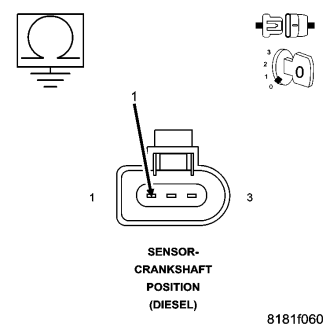
Measure the resistance between ground and the (K853) CKP Sensor 5-Volt Supply circuit at the CKP Sensor harness connector.
Is the resistance above 1000 ohms?
Yes
- Go To 11
No
- Repair the (K853) CKP Sensor 5-Volt Supply circuit for a short to ground.
- Perform the ECM Verification Test Ver. 1. (Refer to 9 - ENGINE - DIAGNOSIS AND TESTING)
11. (K853) CRANKSHAFT POSITION SENSOR 5-VOLT SUPPLY CIRCUIT SHORTED TO THE (K925) CKP SENSOR GROUND CIRCUIT
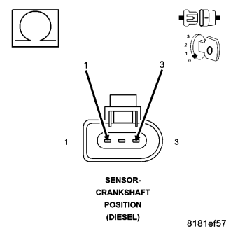
Measure the resistance between the (K853) CKP Sensor 5-Volt Supply circuit and the (K925) CKP Sensor Ground circuit at the CKP Sensor harness connector.
Is the resistance above 1000 ohms?
Yes
- Replace and program the Engine Control Module in accordance with the Service Information.
- Perform the ECM Verification Test Ver. 1. (Refer to 9 - ENGINE - DIAGNOSIS AND TESTING)
No
- Repair the (K853) CKP Sensor 5-Volt Supply circuit and (K925) CKP Sensor Ground circuits for a short together.
- Perform the ECM Verification Test Ver. 1. (Refer to 9 - ENGINE - DIAGNOSIS AND TESTING)
12. (K24) CRANKSHAFT POSITION SENSOR SIGNAL CIRCUIT OPEN
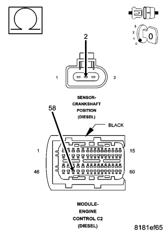
Turn the ignition off.
Disconnect the ECM harness connector.
Measure the resistance of the (K24) CKP Sensor Signal circuit between the ECM harness connector and the CKP Sensor harness connector.
Is the resistance below 10.0 ohms?
Yes
- Go To 13
No
- Repair the (K24) CKP Sensor Signal circuit for an open
- Perform the ECM Verification Test Ver. 1. (Refer to 9 - ENGINE - DIAGNOSIS AND TESTING)
13. (K24) CRANKSHAFT POSITION SENSOR SIGNAL CIRCUIT SHORTED TO GROUND
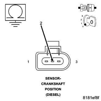
Measure the resistance between ground and the (K24) CKP Sensor Signal circuit at the CKP Sensor harness connector.
Is the resistance above 1000 ohms?
Yes
- Go To 14
No
- Repair the (K24) CKP Sensor Signal circuit for a short to ground.
- Perform the ECM Verification Test Ver. 1. (Refer to 9 - ENGINE - DIAGNOSIS AND TESTING)
14. (K24) CRANKSHAFT POSITION SENSOR SIGNAL CIRCUIT SHORTED TO THE (K925) CKP SENSOR GROUND CIRCUIT
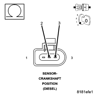
Measure the resistance between the (K24) CKP Sensor Signal circuit and the (K925) CKP Sensor Ground circuit at the CKP Sensor harness connector.
Is the resistance above 1000 ohms?
Yes
- Replace and program the Engine Control Module in accordance with the Service Information.
- Perform the ECM Verification Test Ver. 1. (Refer to 9 - ENGINE - DIAGNOSIS AND TESTING)
No
- Repair the (K24) CKP Sensor Signal circuit and the (K925) CKP Sensor Ground circuit for a short together.
- Perform the ECM Verification Test Ver. 1. (Refer to 9 - ENGINE - DIAGNOSIS AND TESTING)