P0573 BRAKE SWITCH 1 STUCK OFF
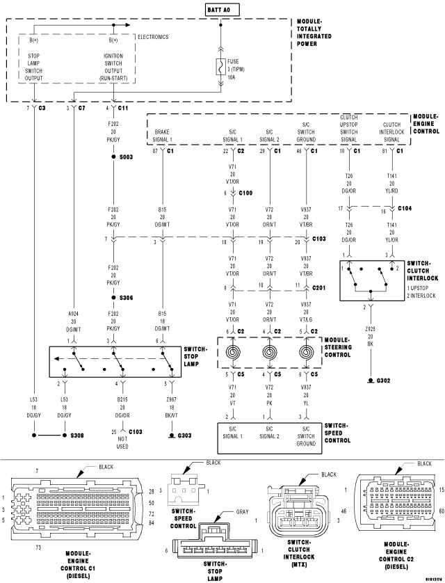
For a complete wiring diagram Refer to Section 8W
- When Monitored:
With the ignition on.
- Set Condition:
The Engine Control Module (ECM) detects that the vehicle has stopped and no brake switch signal was received.
| Possible Causes |
| INTERMITTENT CONDITION |
| BRAKE SWITCH SIGNAL 2 - SWITCH 2 CKT OPEN |
| (A924) FUSED B+ CIRCUIT OPEN |
| (B215) BRAKE SWITCH SIGNAL 2 CIRCUIT SHORTED TO GROUND |
| BRAKE SWITCH SIGNAL 1 - SWITCH 1 CKT OPEN |
| (B215) BRAKE SWITCH SIGNAL 2 CIRCUIT OPEN |
| (Z967) STOP LAMP SWITCH GROUND CIRCUIT OPEN |
| (B15) BRAKE SWITCH SIGNAL 1 CIRCUIT SHORTED TO VOLTAGE |
| (B15) BRAKE SWITCH SIGNAL 1 CIRCUIT OPEN |
| ENGINE CONTROL MODULE - BRAKE SWITCH SIGNAL 2 |
| ENGINE CONTROL MODULE - INTERNAL |
| ENGINE CONTROL MODULE - BRAKE SWITCH SIGNAL 1 |
Always perform the Pre-Diagnostic Troubleshooting procedure before proceeding. (Refer to 9 - ENGINE - DIAGNOSIS AND TESTING)
Diagnostic Test
1. CHECK THE BRAKE SWITCH SIGNAL 1 STATUSTurn the ignition on.
While observing the BRAKE SWITCH SIGNAL 1 status on the scan tool display, press and release the brake pedal several times.
Does the scan tool display BRAKE SWITCH SIGNAL1: PRESSED and RELEASED for the appropriate pedal position?
Yes
- Go To2
No
- Go To11
2. CHECK THE BRAKE SWITCH SIGNAL 2 STATUS
While observing the BRAKE SWITCH SIGNAL 2 status on the scan tool display, press and release the brake pedal several times.
Does the scan tool display BRAKE SWITCH SIGNAL 2: PRESSED and RELEASED for the appropriate pedal position
Yes
- Go To3
No
- Go To4
3. INTERMITTENT CONDITION
WARNING: WHEN THE ENGINE IS OPERATING, DO NOT STAND IN A DIRECT LINE WITH THE FAN. DO NOT PUT YOUR HANDS NEAR THE PULLEYS, BELTS OR FAN. DO NOT WEAR LOOSE CLOTHING.
NOTE: The conditions that set the DTC are not present at this time. The following list may help in identifying the intermittent condition.
With the engine running at normal operating temperature, monitor the scan tool parameters related to the DTC while wiggling the wiring harness. Look for parameter values to change and/or a DTC to set.
Review the DTC When Monitored and Set Conditions. If possible, try to duplicate the conditions under which the DTC was set.
Refer to any Technical Service Bulletins (TSB) that may apply.
Visually inspect the related wiring harness. Look for any chafed, pierced, pinched, or partially broken wires.
Visually inspect the related wiring harness connectors. Look for broken, bent, pushed out, or corroded terminals.
Were any of the above conditions present?
Yes
- Repair as necessary.
- Perform the ECM Verification Test Ver. 1. (Refer to 9 - ENGINE - DIAGNOSIS AND TESTING)
No
- Test Complete.
4. (B215) BRAKE SWITCH SIGNAL 2 CIRCUIT VOLTAGE
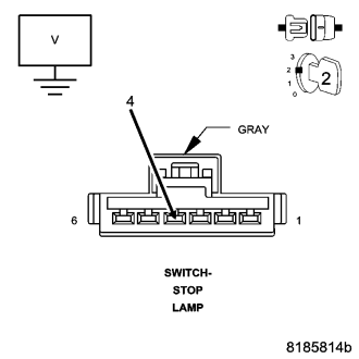
Turn the ignition off.
Disconnect the Stop Lamp Switch harness connector.
Turn the ignition on.
Measure the voltage between the (B215) Brake Switch Signal 2 circuit and ground at the Stop Lamp Switch harness connector.
Is the voltage above 9.0 volts?
Yes
- Go To5
No
- Go To8
5. STOP LAMP SWITCH - BRAKE SWITCH SIGNAL 2 CKT OPEN
While monitoring the BRAKE SWITCH 2 status with the scan tool, connect a jumper wire between ground and the (B215) Brake Switch Signal 2 circuit.
Does the scan tool display change from PRESSED to RELEASED?
Yes
- Adjust or replace the Stop Lamp Switch in accordance with the Service Information.
- Perform the ECM Verification Test Ver. 1. (Refer to 9 - ENGINE - DIAGNOSIS AND TESTING)
No
- Go To6
6. (Z967) STOP LAMP SWITCH GROUND CIRCUIT OPEN
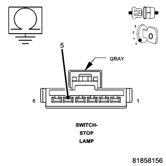
Turn the ignition off.
Disconnect the Stop Lamp Switch harness connector.
Measure the resistance between ground and the (Z967) Stop Lamp Switch Ground circuit at the Stop Lamp Switch harness connector.
Is the resistance below 10.0 ohms?
Yes
- Go To7
No
- Repair the (Z967) Stop Lamp Switch Ground circuit for an open.
- Perform the ECM Verification Test Ver. 1. (Refer to 9 - ENGINE - DIAGNOSIS AND TESTING)
7. ENGINE CONTROL MODULE - INTERNAL
If there are no possible causes remaining, view repair.
Repair
- Replace and program the Engine Control Module in accordance with the Service Information.
- Perform the ECM VERIFICATION TEST. (Refer to 9 - ENGINE - DIAGNOSIS AND TESTING)
8. (B215) BRAKE SWITCH SIGNAL 2 CIRCUIT SHORTED TO GROUND
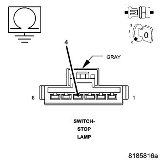
Turn the ignition off.
Disconnect the ECM harness connectors.
Measure the resistance between ground and the (B215) Brake Switch Signal 2 circuit at the Stop Lamp Switch harness connector.
Is the resistance above 1000 ohms?
Yes
- Go To9
No
- Repair the (B215) Brake Switch Signal 2 circuit for a short to ground.
- Perform the ECM Verification Test Ver. 1. (Refer to 9 - ENGINE - DIAGNOSIS AND TESTING)
9. (B215) BRAKE SWITCH SIGNAL 2 CIRCUIT OPEN
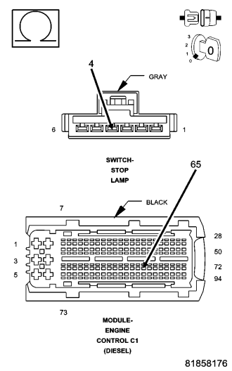
Measure the resistance of the (B215) Brake Switch Signal 2 circuit between the Stop Lamp Switch harness connector and the ECM harness connector.
Is the resistance below 10.0 ohms?
Yes
- Go To10
No
- Repair the (B215) Brake Switch Signal 2 circuit for an open.
- Perform the ECM Verification Test Ver. 1. (Refer to 9 - ENGINE - DIAGNOSIS AND TESTING)
10. ENGINE CONTROL MODULE - BRAKE SWITCH SIGNAL 2
If there are no possible causes remaining, view repair.
Repair
- Replace and program the Engine Control Module in accordance with the Service Information.
- Perform the ECM Verification Test Ver. 1. (Refer to 9 - ENGINE - DIAGNOSIS AND TESTING)
11. (A924) FUSED B+ CIRCUIT OPEN
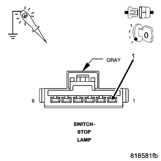
Turn the ignition off.
Disconnect the Stop Lamp Switch harness connector.
Using a 12-volt test light connected to ground, check the (A924) Fused B+ circuit.
Does the test light illuminate brightly?
Yes
- Go To12
No
- Repair the (A924) Fused B+ circuit for an open.
- Perform the ECM Verification Test Ver. 1. (Refer to 9 - ENGINE - DIAGNOSIS AND TESTING)
12. STOP LAMP SWITCH - BRAKE SWITCH SIGNAL 1 OPEN
Turn the ignition on.
While monitoring the BRAKE SWITCH SIGNAL 1 status with the scan tool, connect a jumper wire between the Brake Switch Signal 1 circuit and the Fused B(+) circuit.
Does the scan tool display change from RELEASED to PRESSED?
Yes
- Adjust or replace the Stop Lamp Switch in accordance with the Service Information.
- Perform the ECM Verification Test Ver. 1. (Refer to 9 - ENGINE - DIAGNOSIS AND TESTING)
No
- Go To13
13. (B15) BRAKE SWITCH SIGNAL 1 CIRCUIT SHORTED TO VOLTAGE
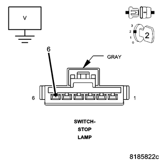
Turn the ignition off.
Disconnect the ECM harness connectors.
Remove the Main Relay.
Connect a jumper wire between cavity B7 and cavity B9 of the Main Relay connector.
Turn the ignition on.
Measure the voltage between the (B15) Brake Switch Signal 1 circuit and ground.
Is the voltage above 1.0 volt?
Yes
- Repair the (B15) Brake Switch Signal 1 circuit for a short to voltage.
- Perform the ECM Verification Test Ver. 1. (Refer to 9 - ENGINE - DIAGNOSIS AND TESTING)
No
- Go To14
14. (B15) BRAKE SWITCH SIGNAL 1 CIRCUIT OPEN
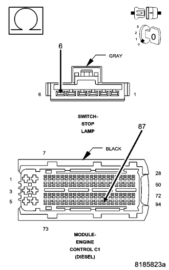
NOTE: Remove the jumper wire.
Turn the ignition off.
Measure the resistance of the (B15) Brake Switch Signal 1 circuit between the Stop Lamp Switch harness connector and the ECM harness connector.
Is the resistance below 10.0 ohms?
Yes
- Replace and program the Engine Control Module in accordance with the Service Information.
- Perform the ECM Verification Test Ver. 1. (Refer to 9 - ENGINE - DIAGNOSIS AND TESTING)
No
- Repair the (B15) Brake Switch Signal 1 circuit for an open.
- Perform the ECM Verification Test Ver. 1. (Refer to 9 - ENGINE - DIAGNOSIS AND TESTING)