P2147-FUEL INJECTOR GROUP 1 SUPPLY VOLTAGE CIRCUIT LOW
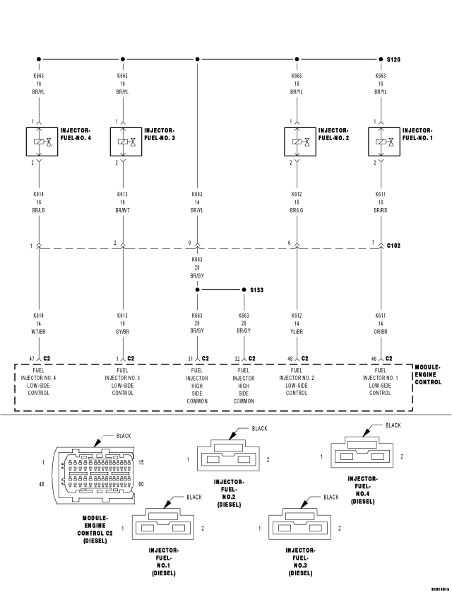
For a complete wiring diagram Refer to Section 8W
- When Monitored:
With the engine running.
- Set Condition:
The ECM detects a short to ground in the fuel injector circuitry.
| Possible Causes |
| INTERMITTENT DTC |
| FUEL INJECTOR HIGH-SIDE CONTROL CIRCUIT SHORTED TO GROUND |
| FUEL INJECTOR LOW-SIDE CONTROL CIRCUIT SHORTED TO GROUND |
| FUEL INJECTOR HIGH-SIDE CONTROL CIRCUIT SHORTED TO FUEL INJECTOR LOW-SIDE CONTROL CIRCUIT |
| FUEL INJECTOR HIGH-SIDE CONTROL CIRCUIT OPEN OR HIGH RESISTANCE |
| FUEL INJECTOR LOW-SIDE CONTROL CIRCUIT OPEN OR HIGH RESISTANCE |
| FUEL INJECTOR |
| ENGINE CONTROL MODULE (ECM) |
Always perform the Pre-Diagnostic Troubleshooting procedure before proceeding. (Refer to 9 - ENGINE - DIAGNOSIS AND TESTING)
Diagnostic Test
1. DTC IS ACTIVENOTE: This DTC can set as a result of a fault in any of the injector circuits. Be sure to check all injector circuits before replacing an injector and all injectors before replacing a module.
Ignition on, engine not running.
With the scan tool, clear DTCs in the Engine Control Module (ECM).
Attempt to start the engine and test drive the vehicle.
With the scan tool, select View DTCs.
Is the status Active for this DTC?
Yes
- Go To 2
No
- Refer to the *CHECKING FOR AN INTERMITTENT DTC Diagnostic Procedure. (Refer to 9 - ENGINE - DIAGNOSIS AND TESTING)
2. FUEL INJECTOR HIGH-SIDE CONTROL CIRCUIT SHORTED TO GROUND
Turn the ignition off.
Disconnect all Fuel Injector harness connectors.
Disconnect the Engine Control Module harness connectors.
Measure the resistance between ground and the Fuel Injector High-Side Control circuit in any Fuel Injector harness connector.
Is the resistance above 1000 ohms?
Yes
- Go to 3
No
- Repair the Fuel Injector High-Side Control circuit for a short to ground.
- Perform the ECM Verification Test Ver. 1. (Refer to 9 - ENGINE - DIAGNOSIS AND TESTING)
3. FUEL INJECTOR LOW-SIDE CONTROL CIRCUIT SHORTED TO GROUND
Measure the resistance between ground and the Fuel Injector Low-Side Control circuit in each Fuel Injector harness connector.
Is the resistance above 1000 ohms for each measurement?
Yes
- Go to 4
No
- Repair the Fuel Injector Low-Side Control circuit for a short to ground.
- Perform the ECM Verification Test Ver. 1. (Refer to 9 - ENGINE - DIAGNOSIS AND TESTING)
4. FUEL INJECTOR HIGH-SIDE CONTROL CIRCUIT SHORTED TO FUEL INJECTOR LOW-SIDE CONTROL CIRCUIT
Measure the resistance between the Fuel Injector High-Side Control circuit and the Fuel Injector Low-Side Control circuit in each Fuel Injector harness connector.
Is the resistance above 1000 ohms between the circuits in each harness connector?
Yes
- Go to 5
No
- Repair the Fuel Injector High-Side Control circuit for a short to the Fuel Injector Low-Side Control circuit.
- Perform the ECM Verification Test Ver. 1. (Refer to 9 - ENGINE - DIAGNOSIS AND TESTING)
5. FUEL INJECTOR HIGH-SIDE CONTROL CIRCUIT OPEN OR HIGH RESISTANCE
Measure the resistance of each Fuel Injector High-Side Control circuit between the Fuel Injector harness connector and the ECM harness connector.
Is the resistance below 10.0 ohms for each measurement?
Yes
- Go to 6
No
- Repair the Fuel Injector High-Side Control circuit for an open circuit or high resistance.
- Perform the ECM Verification Test Ver. 1. (Refer to 9 - ENGINE - DIAGNOSIS AND TESTING)
6. FUEL INJECTOR LOW-SIDE CONTROL CIRCUIT OPEN OR HIGH RESISTANCE
Measure the resistance of each Fuel Injector Low-Side Control circuit between the Fuel Injector harness connector and the ECM harness connector.
Is the resistance below 10.0 ohms for each measurement?
Yes
- Go to 7
No
- Repair the Fuel Injector Low-Side Control circuit for an open circuit or high resistance.
- Perform the ECM Verification Test Ver. 1. (Refer to 9 - ENGINE - DIAGNOSIS AND TESTING)
7. FUEL INJECTOR
Reconnect all connectors.
Disconnect the Fuel Injector 1 harness connector.
Ignition on, engine not running.
With the scan tool, clear DTCs in the Engine Control Module (ECM).
Attempt to start the engine.
With the scan tool, select View DTCs.
NOTE: If this DTC does not reset, replace Fuel Injector 1. If the DTC sets again, repeat this test with Fuel Injector 2, Fuel Injector 3, and Fuel Injector 4.
Did this DTC reset for each disconnected Fuel Injector?
Yes
- Go to 8
No
- Replace the disconnected Fuel Injector in accordance with the Service Information.
- Perform the ECM Verification Test Ver. 1. (Refer to 9 - ENGINE - DIAGNOSIS AND TESTING)
8. ENGINE CONTROL MODULE (ECM)
Using the wiring diagram/schematic as a guide, inspect the wiring and connectors between each Fuel Injector and the Engine Control Module (ECM).
Look for any chafed, pierced, pinched, or partially broken wires.
Look for broken, bent, pushed out or corroded terminals.
Monitor the scan tool data relative to this circuit and wiggle test the wiring and connectors.
Look for the data to change or for the DTC to reset during the wiggle test.
Refer to any Technical Service Bulletins that may apply.
Were any problems found?
Yes
- Repair as necessary.
- Perform the ECM Verification Test Ver. 1. (Refer to 9 - ENGINE - DIAGNOSIS AND TESTING)
No
- Replace the Engine Control Module (ECM) in accordance with the Service Information.
- Perform the ECM Verification Test Ver. 1. (Refer to 9 - ENGINE - DIAGNOSIS AND TESTING)