*NO CRANK CONDITION
For a complete wiring diagram Refer to Section 8W.
| Possible Causes |
| MECHANICAL CONDITION |
| BATTERY CIRCUIT RESISTANCE TOO HIGH |
| START ENABLE CIRCUITS |
| TRANSMISSION RANGE SENSOR |
| FUSED IGNITION SWITCH OUT (START) |
| CLUTCH INTERLOCK SWITCH SIGNAL CIRCUIT |
| CLUTCH INTERLOCK SWITCH GROUND CIRCUIT |
| CLUTCH INTERLOCK SWITCH |
| STARTER |
Diagnostic Test
1. MECHANICAL CONDITIONNOTE: Check and diagnose all the TIPM DTC(s) before continuing.
NOTE: Ensure the Gear selector is in Park or Neutral.
NOTE: Verify the battery is fully charged and capable of passing a load test before continuing.
WARNING: Make sure the battery is disconnected, then wait two minutes before proceeding. Failure to do so may result in personal injury or possible death.
Turn the engine over by hand to make sure the engine is not seized.
Is the engine able to turn over?
Yes
- Go to 2
No
- Repair the mechanical condition preventing the starter motor from cranking.
- Perform the POWERTRAIN VERIFICATION TEST. (Refer to 9 - ENGINE - STANDARD PROCEDURE)
2. EXCESSIVE RESISTANCE IN THE BATTERY CIRCUIT
Connect the battery cables.
Turn the ignition off.
Check the Battery Cables for excessive resistance using the service information procedure.
Did either Battery Cable have a voltage drop greater than 0.2 of a volt?
Yes
- Repair the excessive resistance in the Battery circuit.
- Perform the PCM Verification Test Ver. 1 (Refer to 9 - ENGINE - STANDARD PROCEDURE)
No
- Go to 3
3. MANUAL TRANSMISSION
Is this vehicle equipped with a Manual transmission?
Yes
- Go to 8
No
- Go to 4
4. START ENABLE OPERATION (ATX)
Turn ignition on.
Using a scan tool, monitor the Ignition Start Switch Sense.
Turn the ignition switch to the crank position.
Does the Ignition Start Switch Sense state change from Low to High?
Yes
- Ensure the battery connection is clean and fastened tightly to the Starter. If OK, replace the Starter in accordance with the Service Information.
No
- Go to 5
5. START ENABLE CIRCUIT (ATX)
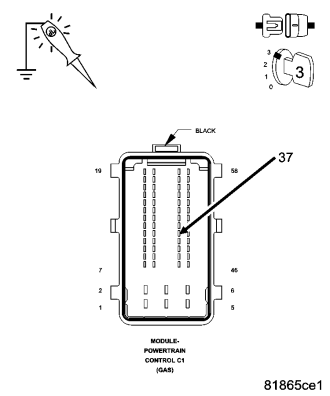
Turn the ignition off.
Disconnect the PCM harness connector.
Using a 12-volt test light connected to ground, probe the Start Enable circuit in the PCM harness connector while holding the ignition key in the start position.
Does the test light illuminate brightly?
Yes
- Replace the PCM in accordance with the Service Information.
- Perform the PCM Verification Test Ver. 1 (Refer to 9 - ENGINE - STANDARD PROCEDURE)
No
- Go to 6
6. TRANSMISSION RANGE SENSOR (ATX)
Turn the ignition off.
Test light still in the above position.
Disconnect the Transmission Range Sensor harness connector.
Using a jumper wire, connect one end to the Start Enable circuit and the other to the Fused Ignition Switch Output (Start) circuit in the Transmission Range Sensor harness connector.
Turn the ignition to the crank position.
Does the test light illuminate brightly?
Yes
- Replace Transmission Range Sensor harness.
- Perform the PCM Verification Test Ver. 1 (Refer to 9 - ENGINE - STANDARD PROCEDURE)
No
- Go to 7
7. FUSED IGNITION SWITCH OUTPUT (START) CIRCUIT (ATX)
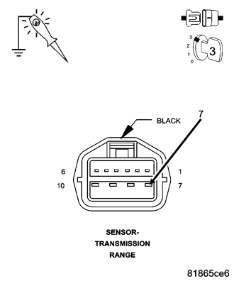
Turn the ignition off.
Using a 12-volt test light connected to ground, probe the Fused Ignition Switch Output (Start) circuit in the Transmission Range Sensor harness connector.
Turn the ignition to the crank position.
Does the test light illuminate brightly?
Yes
- Repair the Start Enable circuit.
- Perform the PCM Verification Test Ver. 1 (Refer to 9 - ENGINE - STANDARD PROCEDURE)
No
- Check the Fused Ignition Switch Output (Start) circuit for an open. If OK, replace the TIPM in accordance with the Service Information.
- Perform the PCM Verification Test Ver. 1 (Refer to 9 - ENGINE - STANDARD PROCEDURE)
8. START ENABLE OPERATION (MTX)
Turn ignition on.
Using a scan tool, monitor the Ignition Start Switch Sense.
Turn the ignition switch to the crank position.
Does the Ignition Start Switch Sense state change from Low to High?
Yes
- Go to 10
No
- Go to 9
9. STATER ENABLE CIRCUIT (MTX)
Turn the ignition off.
Disconnect the PCM harness connector.
Using a 12-volt test light connected to ground, probe the Start Enable circuit in the PCM harness connector while holding the ignition key in the start position.
Does the test light illuminate brightly?
Yes
- Replace the PCM in accordance with the Service information.
- Perform the PCM Verification Test Ver. 1 (Refer to 9 - ENGINE - STANDARD PROCEDURE)
No
- Check the Start Enable circuit . If OK, replace the TIPM in accordance with the Service Information.
- Perform the PCM Verification Test Ver. 1 (Refer to 9 - ENGINE - STANDARD PROCEDURE)
10. CLUTCH INTERLOCK OPERATION (MTX)
Turn ignition on.
Using a scan tool, monitor the Clutch Switch.
Press the Clutch in and out.
Does Clutch Switch display Released and then Pressed?
Yes
- Replace the Starter in accordance with the Service Information.
- Perform the PCM Verification Test Ver. 1 (Refer to 9 - ENGINE - STANDARD PROCEDURE)
No
- Go to 11
11. CLUTCH INTERLOCK OPERATION (MTX)
Turn the ignition off.
Disconnect the PCM harness connector.
Using a 12-volt test light connected to battery voltage, probe the Clutch interlock Signal circuit in the PCM harness connector while pressing the clutch pedal in.
Does the test light illuminate brightly?
Yes
- Replace the PCM in accordance with the Service information.
- Perform the PCM Verification Test Ver. 1 (Refer to 9 - ENGINE - STANDARD PROCEDURE)
No
- Go to 12
12. CLUTCH INTERLOCK SWITCH (MTX)
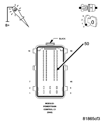
Turn the ignition off.
Test light still in the above position.
Disconnect the Clutch Interlock Switch harness connector.
Using a jumper wire, connect one end to the Clutch Interlock Switch Signal circuit and the other to the Clutch Interlock Switch ground circuit in the Clutch Interlock Switch harness connector.
Does the test light illuminate brightly?
Yes
- Replace Clutch Interlock Switch.
- Perform the PCM Verification Test Ver. 1 (Refer to 9 - ENGINE - STANDARD PROCEDURE)
No
- Go to 13
13. CLUTCH INTERLOCK OPERATION (MTX)
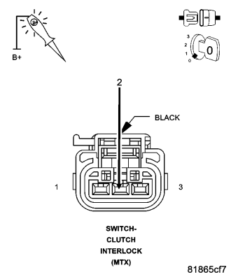
Remove the jumper wire.
Using a 12-volt test light connected to battery voltage, probe the Clutch Interlock Switch ground circuit.
Does the test light illuminate brightly?
Yes
- Repair the Clutch Interlock Switch ground circuit.
- Perform the PCM Verification Test Ver. 1 (Refer to 9 - ENGINE - STANDARD PROCEDURE)
No
- Repair the Clutch Interlock Switch signal circuit.
- Perform the PCM Verification Test Ver. 1 (Refer to 9 - ENGINE - STANDARD PROCEDURE)