*NO RESPONSE WITH A NO START CONDITION
For a complete wiring diagram Refer to Section 8W.
| Possible Causes |
| (A931) FUSED B+ CIRCUIT (PCM) |
| (F202) FUSED IGNITION SWITCH OUTPUT (RUN-START) CIRCUITS (PCM) |
| (Z925) PCM GROUND CIRCUITS (PCM) |
| (K51) MAIN RELAY CONTROL CIRCUIT |
| (A14) FUSED B+ CIRCUIT (MAIN RELAY) |
| (A935) FUSED B+ CIRCUIT (MAIN RELAY) |
| (K542) MAIN RELAY OUTPUT CIRCUIT (TO TIPM) |
| (F342/F343/344) MAIN RELAY OUTPUT CIRCUIT (TO PCM) |
| TIPM |
| PCM |
Diagnostic Test
1. (A931) FUSED B+ CIRCUIT (PCM)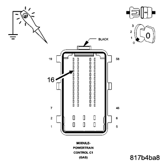
NOTE: The scan tool and cable must be operating properly for the results of this test to be valid.
NOTE: Make sure the ignition switch was on while trying to communicate with the PCM.
Turn the ignition off.
Disconnect the C1 PCM harness connectors.
Using a 12-volt test light connected to ground, probe the (A931) Fused B+ circuit in the PCM harness connector.
NOTE: The test light should be illuminated and bright. Compared the brightness to that of a direct connection to the battery.
Does the test light illuminate brightly?
Yes
- Go to 2
No
- Repair the open or short to ground in the (A931) Fused B+ circuit. Inspect and replace fuses as necessary.
- Perform the PCM Verification Test Ver. 1 (Refer to 9 - ENGINE - STANDARD PROCEDURE)
2. (F202) IGNITION SWITCH OUTPUT (RUN-START) CIRCUITS (PCM)
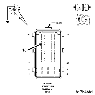
Turn the ignition on.
Using a 12-volt test light connected to ground, probe the (F202) Fused Ignition Switch Output circuit in the PCM harness connector.
Turn the ignition to run.
NOTE: The test light should be illuminated and bright. Compared the brightness to that of a direct connection to the battery.
Does the test light illuminate brightly?
Yes
- Go to 3
No
- Repair the (F202) Ignition Switch Output circuits. Inspect and replace fuses as necessary.
- Perform the PCM Verification Test Ver. 1 (Refer to 9 - ENGINE - STANDARD PROCEDURE)
3. (Z925) GROUND CIRCUITS (PCM)
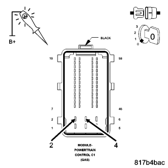
Turn the ignition off.
Using a 12-volt test light connected to battery voltage, probe both the (Z925) PCM ground circuits
NOTE: The test light should be illuminated and bright. Compared the brightness to that of a direct connection to the battery.
Does the test light illuminate brightly at both terminals?
Yes
- Go to 4
No
- Repair the Ground circuit(s).
- Perform the PCM Verification Test Ver. 1 (Refer to 9 - ENGINE - STANDARD PROCEDURE)
4. (A14) FUSED B+ CIRCUIT (MAIN RELAY)
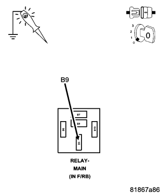
Turn the ignition off.
Remove the Main Relay.
Using a 12-volt test light connected to ground, probe the (A14) Fused B+ circuit at the Main Relay terminal.
NOTE: The test light should be illuminated and bright. Compared the brightness to that of a direct connection to the battery.
Does the test light illuminate brightly?
Yes
- Go to 5
No
- Repair the (A14) Fused B+ circuit.
- Perform the PCM Verification Test Ver. 1 (Refer to 9 - ENGINE - STANDARD PROCEDURE)
5. (A935) FUSED B+ CIRCUIT (MAIN RELAY)
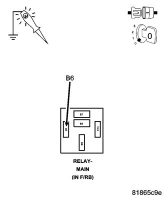
Using a 12-volt test light connected to ground, probe the (A935) Fused B+ circuit at the Main Relay terminal.
NOTE: The test light should be illuminated and bright. Compared the brightness to that of a direct connection to the battery.
Does the test light illuminate brightly?
Yes
- Go to 6
No
- Repair the (A935) Fused B+ circuit.
- Perform the PCM Verification Test Ver. 1 (Refer to 9 - ENGINE - STANDARD PROCEDURE)
6. (F342) MAIN RELAY OUTPUT CIRCUITS
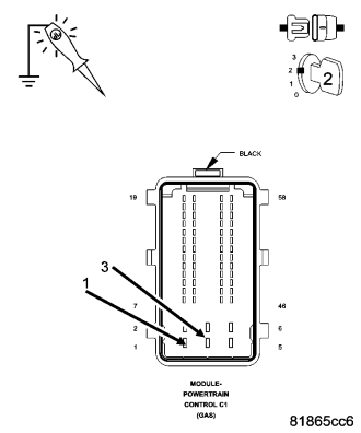
Turn the ignition on.
Using a jumper wire, jumper across the Main Relay from (K542) Main Relay Output circuit and the (A14) Fused B+ circuit.
With a 12-volt test light connected to ground, probe the (F342) Main Relay Output circuits in the PCM harness connector.
NOTE: The test light should be illuminated and bright. Compared the brightness to that of a direct connection to the battery.
Does the test light illuminate brightly at both terminals?
Yes
- Go to 8
No
- Go to 7
7. (K542) MAIN RELAY OUTPUT CIRCUIT
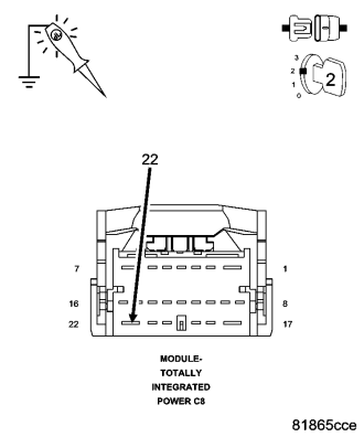
Jumper wire still installed.
Disconnect the C8 TIPM harness connector.
Using a 12-volt test light connected to ground, probe the (K542) Main Relay Output circuit in the TIPM harness connector.
NOTE: The test light should be illuminated and bright. Compared the brightness to that of a direct connection to the battery.
Does the test light illuminate brightly?
Yes
- Repair the (K542) Main Relay Output circuit between the TIPM and the Main Relay. Inspect the related fuses.
- Perform the PCM Verification Test Ver. 1 (Refer to 9 - ENGINE - STANDARD PROCEDURE)
No
- Repair the (F342) Main Relay Output circuit(s).
- Perform the PCM Verification Test Ver. 1 (Refer to 9 - ENGINE - STANDARD PROCEDURE)
8. MAIN RELAY OUTPUT
Turn the ignition off.
Remove one end of the jumper wire.
Connect the PCM harness connector.
Turn the ignition on.
Return the jumper wire across the Main Relay.
Using a scan tool, attempt to communication with the PCM.
Were you able to communication with the PCM?
Yes
- Go to 9
No
- Go to 11
9. MAIN RELAY
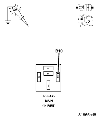
NOTE: To continue the following test, leave the jumper wire in place with the ignition on.
Using the scan tool, actuate the Main Relay.
Using a 12-volt test light connected to battery voltage, probe the (K51) Main Relay Control circuit in the Main Relay connector.
Does the test light illuminate and flash on and off?
Yes
- Replace the Main Relay.
- Perform the PCM Verification Test Ver. 1 (Refer to 9 - ENGINE - STANDARD PROCEDURE)
No
- Go to 10
10. (K51) MAIN RELAY CONTROL CIRCUIT
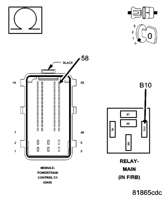
Turn the ignition off.
Disconnect the PCM harness connector.
Disconnect the C1 PCM harness connector.
Measure the resistance of the (K51) Main Relay Control circuit between the PCM harness connector and the Main relay connector.
Is the resistance below 5.0 ohms?
Yes
- Repair the open in the (K51) Main Relay Control circuit.
- Perform the PCM Verification Test Ver. 1 (Refer to 9 - ENGINE - STANDARD PROCEDURE)
No
- Replace and program the Powertrain Control Module per Service Information.
- Perform the PCM Verification Test Ver. 1 (Refer to 9 - ENGINE - STANDARD PROCEDURE)
11. (D65) CAN C BUS (+) CIRCUIT OPEN
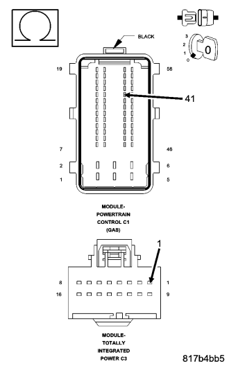
Turn the ignition off.
Disconnect the TIPM harness connector.
Measure the resistance of the (D65) CAN C Bus (+) circuit between the TIPM connector and the PCM harness connector.
Is the resistance below 5.0 ohms?
Yes
- Go to 12
No
- Repair the (D65) CAN C Bus (+) circuit for an open.
- Perform the PCM Verification Test Ver. 1 (Refer to 9 - ENGINE - STANDARD PROCEDURE)
12. (D64) CAN C BUS (-) CIRCUIT OPEN
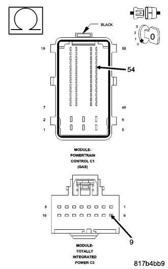
Measure the resistance of the (D64) CAN C Bus (-) circuit between the TIPM connector and the PCM harness connector.
Is the resistance below 5.0 ohms?
Yes
- Replace and program the Powertrain Control Module in accordance with the service information.
- Perform the PCM Verification Test Ver. 1 (Refer to 9 - ENGINE - STANDARD PROCEDURE)
No
- Repair the (D64) CAN C Bus (-) circuit for an open.
- Perform the PCM Verification Test Ver. 1 (Refer to 9 - ENGINE - STANDARD PROCEDURE)