P0196-ENGINE OIL TEMPERATURE SENSOR PERFORMANCE
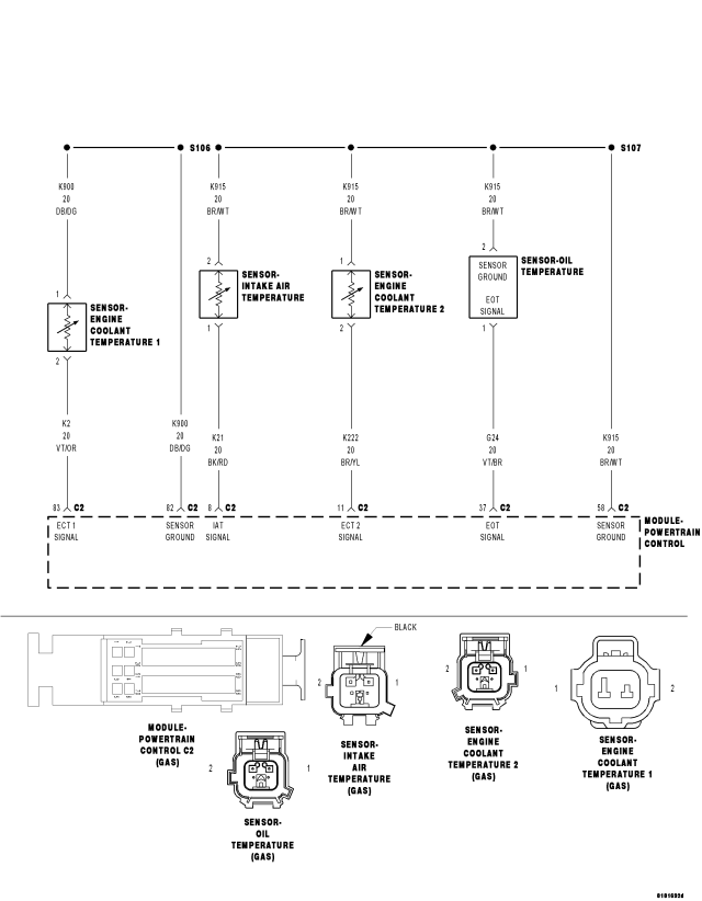
For a complete wiring diagram Refer to Section 8W
Theory of Operation
The PCM compares engine coolant temperature (ECT), intake air temperature (IAT), and ambient air temperature (AAT) under cold start conditions. Following a start to run delay time, the sensor values are compared. If the one sensor value is not within a specified range of the other two sensors, the value is determined to be irrational. Once the general temperature rationality is passed, the PCM determines that the general temperature sensor values are correct. The PCM compares the Oil Temperature Sensor value to a threshold based on the other temp sensor values. If the difference is greater than a calibrated value, the diagnostic fails.
- When Monitored:
With engine off time greater than 480 minutes and ambient temperature greater than – 7° C (19.4° F).
- Set Condition:
After a calibrated amount of cool down time, the PCM compares the AAT, ECT, and IAT Sensor values. If the general temperature rationality passes, the PCM compares the Oil Temperature Sensor value to a threshold based on the other temp sensor values. If the difference is greater than a calibrated value, the diagnostic fails.
| Possible Causes |
| INTERMITTENT DTC |
| (G24) EOT SIGNAL CIRCUIT SHORTED TO VOLTAGE |
| (G24) EOT SIGNAL CIRCUIT SHORTED TO GROUND |
| (G24) EOT SIGNAL CIRCUIT SHORTED TO (K915) SENSOR GROUND CIRCUIT |
| (G24) EOT SIGNAL CIRCUIT OPEN OR HIGH RESISTANCE |
| (K915) SENSOR GROUND CIRCUIT OPEN OR HIGH RESISTANCE |
| ENGINE OIL TEMPERATURE SENSOR |
| POWERTRAIN CONTROL MODULE (PCM) |
Always perform the Pre-Diagnostic Troubleshooting procedure before proceeding. (Refer to 9 - ENGINE - STANDARD PROCEDURE)
Diagnostic Test
1. DTC IS ACTIVENOTE: Diagnose any CAN - C Communication DTCs before continuing.
Turn the ignition off.
If possible, allow the vehicle to sit with the ignition off for more than 480 minutes in an environment where the temperature is consistent and above – 7° C (19.4° F).
Test drive the vehicle. The vehicle must exceed 48 km/h (30 mph) during the test drive. Do not cycle the ignition off when the test drive is completed.
With a scan tool, select View DTCs.
Is the status Active or Pending for this DTC?
Yes
- Go To 3
No
- Go to 2
2. AMBIENT AIR TEMPERATURE
Turn the ignition off.
Allow the vehicle to sit with the ignition off in an environment where the temperature is consistent and above – 7° C (19.4° F) until the engine coolant temperature is equal to ambient temperature.
Turn the ignition on.
With a scan tool, compare the Engine Oil Temperature Sensor value to the AAT, ECT, and IAT sensor values.
Is the Engine Oil Temperature Sensor value within 10° C (18° F) of the other sensor values?
Yes
- Refer to the *CHECKING FOR AN INTERMITTENT DTC Diagnostic Procedure. (Refer to 9 - ENGINE - DIAGNOSIS AND TESTING)
No
- Go to 3
3. (G24) EOT SIGNAL CIRCUIT SHORTED TO VOLTAGE
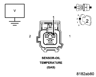
Turn the ignition off.
Disconnect the Engine Oil Temperature Sensor connector.
Disconnect the Powertrain Control Module (PCM) connector.
Turn the ignition on.
Measure the voltage of the (G24) EOT Signal circuit in the Engine Oil Temperature Sensor harness connector.
Is there any voltage present?
Yes
- Repair the (G24) EOT Signal circuit for a short to voltage.
- Perform the PCM Verification Test Ver. 1 (Refer to 9 - ENGINE - STANDARD PROCEDURE).
No
- Go to 4
4. (G24) EOT SIGNAL CIRCUIT SHORTED TO GROUND
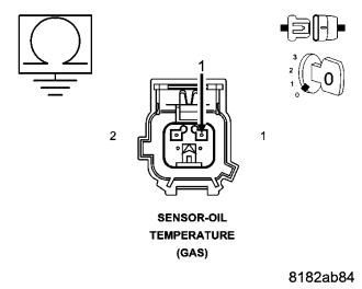
Turn the ignition off.
Measure the resistance between ground and the (G24) EOT Signal circuit in the Engine Oil Temperature Sensor harness connector.
Is the resistance above 100 ohms?
Yes
- Go to 5
No
- Repair the (G24) EOT Signal circuit for a short to ground.
- Perform the PCM Verification Test Ver. 1 (Refer to 9 - ENGINE - STANDARD PROCEDURE).
5. (G24) EOT SIGNAL CIRCUIT SHORTED TO (K915) SENSOR GROUND CIRCUIT
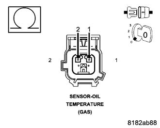
Measure the resistance between the (G24) EOT Signal circuit and the (K915) Sensor Ground circuit in the Engine Oil Temperature Sensor harness connector.
Is the resistance above 100 ohms?
Yes
- Go to 6
No
- Repair the (G24) EOT Signal circuit for a short to the (K915) Sensor Ground circuit.
- Perform the PCM Verification Test Ver. 1 (Refer to 9 - ENGINE - STANDARD PROCEDURE).
6. (G24) EOT SIGNAL CIRCUIT OPEN OR HIGH RESISTANCE
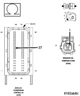
Measure the resistance of the (G24) EOT Signal circuit between the Engine Oil Temperature Sensor harness connector and the Powertrain Control Module (PCM) harness connector.
Is the resistance below 5.0 ohms?
Yes
- Go to 7
No
- Repair the (G24) EOT Signal circuit for an open circuit or high resistance.
- Perform the PCM Verification Test Ver. 1 (Refer to 9 - ENGINE - STANDARD PROCEDURE).
7. (K915) SENSOR GROUND CIRCUIT OPEN OR HIGH RESISTANCE
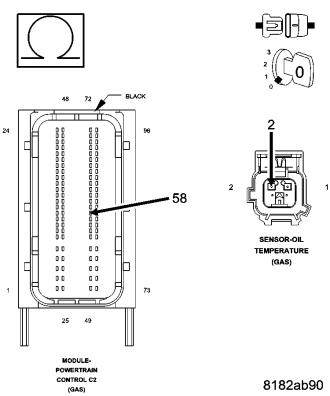
Measure the resistance of the (K915) Sensor Ground circuit between the Engine Oil Temperature Sensor harness connector and the Powertrain Control Module (PCM) harness connector.
Is the resistance below 5.0 ohms?
Yes
- Go to 8
No
- Repair the (K915) Sensor Ground for an open circuit or high resistance.
- Perform the PCM Verification Test Ver. 1 (Refer to 9 - ENGINE - STANDARD PROCEDURE).
8. ENGINE OIL TEMPERATURE SENSOR
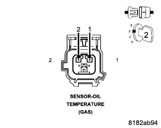
Turn the ignition off.
Connect the Powertrain Control Module (PCM) connector.
Connect a jumper wire between the (K915) Sensor Ground circuit and the (G24) EOT Signal circuit in the Engine Oil Temperature Sensor harness connector.
Turn the ignition on.
With the scan tool, read the Engine Oil Temperature Sensor signal voltage.
Is the voltage below 1.0 volt with the jumper wire in place?
Yes
- Replace the Engine Oil Temperature Sensor in accordance with the Service Information.
- Perform the PCM Verification Test Ver. 1 (Refer to 9 - ENGINE - STANDARD PROCEDURE).
No
- Go to 9
9. POWERTRAIN CONTROL MODULE (PCM)
Using the wiring diagram/schematic as a guide, inspect the wiring and connectors between the Engine Oil Temperature Sensor and the Powertrain Control Module (PCM).
Look for any chafed, pierced, pinched, or partially broken wires.
Look for broken, bent, pushed out or corroded terminals.
Monitor the scan tool data relative to this circuit and wiggle test the wiring and connectors.
Look for the data to change or for the DTC to reset during the wiggle test.
Refer to any Technical Service Bulletins that may apply.
Were any problems found?
Yes
- Repair as necessary.
- Perform the PCM Verification Test Ver. 1 (Refer to 9 - ENGINE - STANDARD PROCEDURE).
No
- Replace and program the Powertrain Control Module (PCM) in accordance with the Service Information.
- Perform the PCM Verification Test Ver. 1 (Refer to 9 - ENGINE - STANDARD PROCEDURE).