P0440-GENERAL EVAP SYSTEM FAILURE
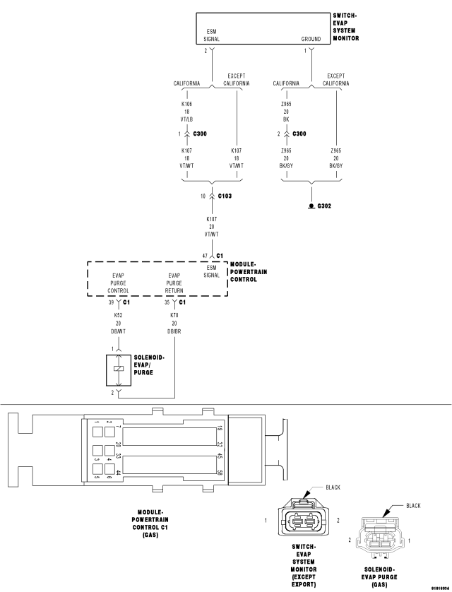
For a complete wiring diagram Refer to Section 8W.
- When Monitored:
With the engine running after a cold start, the difference between ECT and AAT less than 10° C (18° F), fuel level between 12% and 88%, manifold vacuum greater than a minimum value, ambient temperature between 4° C and 37° C (39° F and 89° F) and altitude less than 8500 feet.
- Set Condition:
When the monitor conditions are met, the PCM will ramp in purge flow. If the PCM does not sense an ESM switch closure after a calculated amount of purge flow accumulation, an error is detected. Two Trip Fault. Three good trips to turn off the MIL.
| Possible Causes |
| INTERMITTENT DTC |
| EVAP PURGE SOLENOID VACUUM SUPPLY |
| EVAP SYSTEM LEAK |
| EVAP PURGE HOSE/TUBE OBSTRUCTION |
| (Z914) GROUND CIRCUIT OPEN OR HIGH RESISTANCE |
| (K107) ESM SIGNAL CIRCUIT OPEN OR HIGH RESISTANCE |
| EVAP PURGE SOLENOID |
| EVAPORATIVE SYSTEM MONITOR SWITCH |
| POWERTRAIN CONTROL MODULE (PCM) |
Always perform the Pre-Diagnostic Troubleshooting procedure before proceeding. (Refer to 9 - ENGINE - DIAGNOSIS AND TESTING).
1. DTC IS ACTIVE
NOTE: Allow the vehicle to cool to ambient temperature before continuing with this procedure.
NOTE: A loose gas cap may have caused this DTC to set. Make sure gas cap is tight and in good condition. Make sure the gas cap meets OEM specifications.
Start the engine.
Allow the engine to idle.
Using the scan tool, perform the ESIM FORCED MONITOR TEST. Allow the test to complete.
With a scan tool, select View DTCs.
Is the status Active for this DTC?
Yes
- Go to 2
No
- Refer to the *CHECKING FOR AN INTERMITTENT DTC Diagnostic Procedure. (Refer to 9 - ENGINE - DIAGNOSIS AND TESTING)
2. EVAP SYSTEM INSPECTION
Inspect the Evap System for any of the following conditions:
- Holes or cracks
- Loose seal points
- Damaged or missing components
- Incorrect routing of hoses and tubes
- Loose or missing fuel cap
- Damaged or missing fuel cap seal
- Improper installation of the fuel cap
- Damaged locking tabs on the fuel cap and/or filler tube
- Damaged seal points on the fuel cap and/or filler tube
Were any problems found?
Yes
- Repair as necessary.
- Perform the PCM Verification Test. (Refer to 9 - ENGINE - STANDARD PROCEDURE)
No
- Go to 3
3. INSUFFICIENT VACUUM SUPPLY TO THE EVAP PURGE SOLENOID
Inspect the Evap Purge Solenoid vacuum supply hose for proper routing and installation.
Make sure the vacuum supply hose between the throttle body or intake manifold and the Evap Purge Solenoid is free from any contamination, obstructions or blockage.
Make sure the Evap Purge Solenoid and purge lines are free from any contamination, obstructions or blockage.
Make sure the vacuum port at the throttle body or intake manifold is free from any contamination, obstructions or blockage.
Were any problems found?
Yes
- Repair as necessary.
- Perform the PCM Verification Test. (Refer to 9 - ENGINE - STANDARD PROCEDURE)
No
- Go to 4
4. EVAP PURGE SOLENOID
Disconnect the purge lines at the Evap Purge Solenoid.
Using a hand vacuum pump, apply 10 inHg of vacuum to the "CAN" side of the Evap Purge Solenoid.
NOTE: The solenoid should hold vacuum for a minimum of 15 seconds.
Turn the ignition on.
With the scan tool, actuate the Evap Purge Solenoid to the ON position.
NOTE: The vacuum should drop when the solenoid is actuated.
Does the solenoid function as described above?
Yes
- Go to 5
No
- Replace the Evap Purge Solenoid.
- Perform the PCM Verification Test. (Refer to 9 - ENGINE - STANDARD PROCEDURE)
5. EVAPORATIVE SYSTEM MONITOR SWITCH STATE
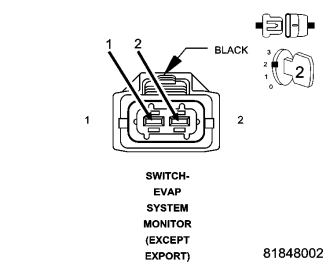
Turn the ignition off.
Disconnect the Evaporative System Monitor Switch harness connector.
Turn the ignition on.
Read the Evaporative System Monitor Switch state on the scan tool.
Carefully connect a jumper wire between the (K107) ESM Signal circuit and the (Z914) Ground circuit in the Evap System Monitor Switch harness connector.
Read the Evaporative System Monitor Switch state on the scan tool.
Does the switch change from OPEN to CLOSED with the jumper in place?
Yes
- Go to 8
No
- Go to 6
6. (K107) ESM SIGNAL CIRCUIT OPEN OR HIGH RESISTANCE
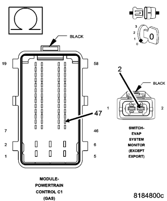
Turn the ignition off.
Disconnect the Powertrain Control Module (PCM) harness connectors.
CAUTION: Do not probe the PCM harness connectors. Probing the PCM harness connectors will damage the PCM terminals, resulting in poor terminal to pin connection. Install Miller Special Tool #8815 to perform diagnosis.
Measure the resistance of the (K107) ESM Signal between the Evaporative System Monitor Switch harness connector and the appropriate terminal of special tool #8815.
Is the resistance below 5.0 ohms?
Yes
- Go to 7
No
- Repair the (K107) ESM Signal circuit for an open circuit or high resistance.
- Perform the PCM Verification Test. (Refer to 9 - ENGINE - STANDARD PROCEDURE)
7. (Z914) GROUND CIRCUIT OPEN OR HIGH RESISTANCE
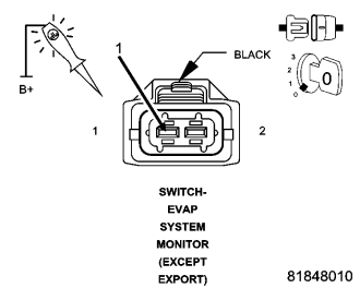
Turn the ignition off.
Using a 12 volt test light connected to 12 volts, check the (Z914) Ground circuit in the Evaporative System Monitor Switch harness connector.
NOTE: The test light should be illuminate and bright. Compare the brightness to that of a direct connection to the battery.
Is the test light illuminated and bright?
Yes
- Go to 11
No
- Repair the (Z914) Ground circuit for an open circuit or high resistance.
- Perform the PCM Verification Test. (Refer to 9 - ENGINE - STANDARD PROCEDURE)
8. EVAP PURGE HOSE/TUBE OBSTRUCTION
Inspect the Evap Purge hose/tube between the Evap Purge Solenoid and the Fuel Tank and between the Fuel Tank and the Evap Purge Canister for proper routing and installation.
Make sure the hoses and tubes are not damaged, kinked, or blocked.
Were any problems found?
Yes
- Repair or replace as necessary.
- Perform the PCM Verification Test. (Refer to 9 - ENGINE - STANDARD PROCEDURE)
No
- Go to 9
9. CHECKING THE EVAPORATIVE SYSTEM FOR LEAKS
Perform the diagnostic procedure for *CHECKING THE EVAPORATIVE SYSTEM FOR LEAKS.
Were any problems found?
Yes
- Repair as necessary in accordance with the Service Information.
- Perform the PCM Verification Test. (Refer to 9 - ENGINE - STANDARD PROCEDURE)
No
- Go to 10
10. EVAPORATIVE SYSTEM MONITOR SWITCH
Using the wiring diagram/schematic as a guide, inspect the wiring and connectors between the Evaporative System Monitor Switch and the Powertrain Control Module (PCM).
Look for any chafed, pierced, pinched, or partially broken wires.
Look for broken, bent, pushed out or corroded terminals.
Refer to any Technical Service Bulletins that may apply.
Were any problems found?
Yes
- Repair as necessary.
- Perform the PCM Verification Test. (Refer to 9 - ENGINE - STANDARD PROCEDURE)
No
- Replace the Evaporative System Monitor Switch in accordance with the Service Information.
- Perform the PCM Verification Test. (Refer to 9 - ENGINE - STANDARD PROCEDURE)
11. POWERTRAIN CONTROL MODULE (PCM)
Using the wiring diagram/schematic as a guide, inspect the wiring and connectors between the Evaporative System Monitor Switch and the Powertrain Control Module (PCM).
Look for any chafed, pierced, pinched, or partially broken wires.
Look for broken, bent, pushed out or corroded terminals.
Refer to any Technical Service Bulletins that may apply.
Were any problems found?
Yes
- Repair as necessary.
- Perform the PCM Verification Test. (Refer to 9 - ENGINE - STANDARD PROCEDURE)
No
- Replace and program the Powertrain Control Module (PCM) in accordance with the Service Information.
- Perform the PCM Verification Test. (Refer to 9 - ENGINE - STANDARD PROCEDURE)