P2066-FUEL LEVEL SENSOR 2 PERFORMANCE
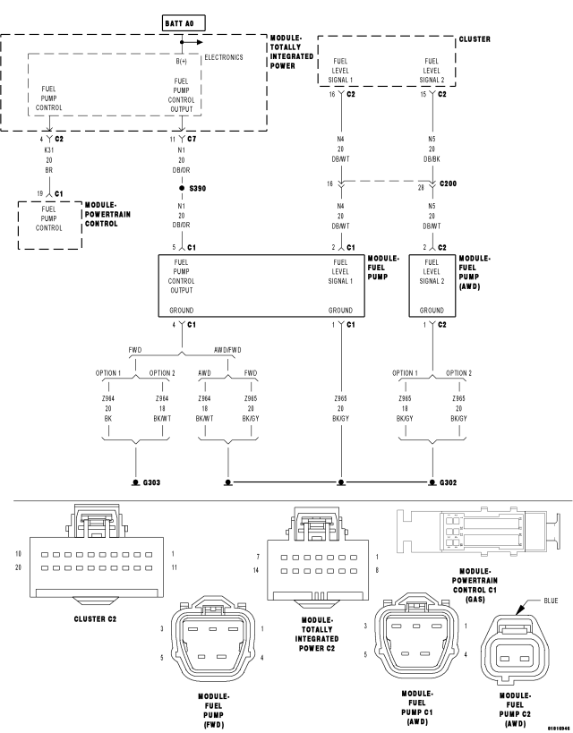
For a complete wiring diagram Refer to Section 8W
Theory of Operation
Vehicles with saddle fuel tank configurations have two fuel level sending units. The primary side of the tank has the filler tube inlet near the bottom and contains the fuel pump module. During fuel tank fills, fuel must overflow the primary side to reach the secondary side. As fuel is consumed, a siphon tube is used to draw fuel from the secondary side to the primary side. Because the siphon tube flow rate exceeds the fuel consumption rate, the secondary side of the tank will be empty before fuel is depleted from the primary side. The rationality for each fuel level sensor is based on the float position of the opposite side of the tank. The primary sensor rationality is enabled when the secondary level is near the bottom of the tank. The secondary sensor rationality is enabled before the primary side begins to show fuel consumption or fuel volume is greater than a calibrated volume.
- When Monitored:
With engine run time greater than 128 seconds.
- Set Condition:
The PCM detects no change in Fuel Level Sensor 2 circuit voltage over time during monitoring.
| Possible Causes |
| INTERMITTENT DTC |
| FUEL PUMP MODULE WIRING OR CONNECTORS |
| INTERIOR OR EXTERIOR FUEL TANK DAMAGE |
| (N5) FUEL LEVEL SIGNAL 2 CIRCUIT SHORTED TO VOLTAGE |
| (N5) FUEL LEVEL SIGNAL 2 CIRCUIT SHORTED TO GROUND |
| (N5) FUEL LEVEL SIGNAL 2 CIRCUIT OPEN OR HIGH RESISTANCE |
| (N4) FUEL LEVEL SIGNAL 1 CIRCUIT SHORTED TO VOLTAGE |
| (N4) FUEL LEVEL SIGNAL 1 CIRCUIT SHORTED TO GROUND |
| (N4) FUEL LEVEL SIGNAL 1 CIRCUIT OPEN OR HIGH RESISTANCE |
| (Z965) GROUND CIRCUIT OPEN OR HIGH RESISTANCE |
| (Z912) GROUND CIRCUIT OPEN OR HIGH RESISTANCE |
| FUEL LEVEL SENSOR 2 |
| FUEL LEVEL SENSOR 1 |
| INSTRUMENT CLUSTER (CCN) |
Always perform the Pre-Diagnostic Troubleshooting procedure before proceeding. (Refer to 9 - ENGINE - STANDARD PROCEDURE)
Diagnostic Test
1. DTC IS ACTIVETurn the ignition on.
With the scan tool, select View DTCs and review the DTC environmental information.
Is the good trip counter greater than 0?
Yes
- The DTC is not active at this time. Refer to the *CHECKING FOR AN INTERMITTENT DTC Diagnostic Procedure. (Refer to 9 - ENGINE - DIAGNOSIS AND TESTING)
No
- Go to 2
2. EXTERIOR FUEL TANK DAMAGE
Inspect the exterior of the fuel tank for any damage that may restrict the movement of the fuel level sensor floats.
Were any problems found?
Yes
- Replace the fuel tank as necessary.
- Perform the Body Verification Test Ver. 1 (Refer to 8 - ELECTRICAL/ELECTRONIC CONTROL MODULES)
No
- Go to 3
3. FUEL PUMP MODULE WIRING AND CONNECTORS
Using the wiring diagram/schematic as a guide, inspect the wiring and connectors between the Fuel Pump Module harness connector and the Instrument Cluster (CCN).
Look for any chafed, pierced, pinched, or partially broken wires.
Look for broken, bent, pushed out or corroded terminals.
Refer to any Technical Service Bulletins that may apply.
Were any problems found?
Yes
- Repair as necessary.
- Perform the Body Verification Test Ver. 1 (Refer to 8 - ELECTRICAL/ELECTRONIC CONTROL MODULES)
No
- Go to 4
4. (N5) FUEL LEVEL SIGNAL 2 CIRCUIT VOLTAGE
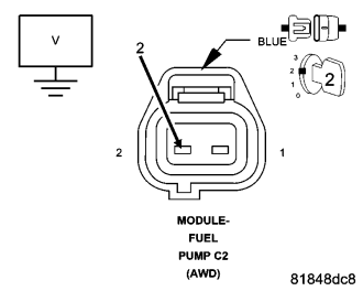
Turn the ignition off.
Disconnect the Fuel Pump Module harness connector.
Turn the ignition on.
With the scan tool, read the Fuel Level Sensor 2 circuit voltage.
NOTE: The sensor voltage should be approximately 5.0 volts (plus or minus .1 volt) with connector disconnected.
Turn the ignition off.
Connect a jumper wire between ground and the (N5) Fuel Level Signal 2 circuit in the Fuel Pump Module harness connector.
Turn the ignition on.
With the scan tool, read the Fuel Level Sensor 2 circuit voltage.
NOTE: The sensor voltage should be approximately 0.0 volts (plus or minus .1 volt) with the jumper wire in place.
Does the scan tool display the voltage as described above?
Yes
- Go to 5
No
- Go to 11
5. (N4) FUEL LEVEL SIGNAL 1 CIRCUIT VOLTAGE
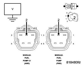
With the scan tool, read the Fuel Level Sensor 1 circuit voltage.
NOTE: The sensor voltage should be approximately 5.0 volts (plus or minus .1 volt) with connector disconnected.
Turn the ignition off.
Connect a jumper wire between ground and the (N4) Fuel Level Signal 1 circuit in the Fuel Pump Module harness connector.
Turn the ignition on.
With the scan tool, read the Fuel Level Sensor 1 circuit voltage.
NOTE: The sensor voltage should be approximately 0.0 volts (plus or minus .1 volt) with the jumper wire in place.
Does the scan tool display the voltage as described above?
Yes
- Go to 6
No
- Go to 14
6. (Z965) GROUND CIRCUIT OPEN OR HIGH RESISTANCE
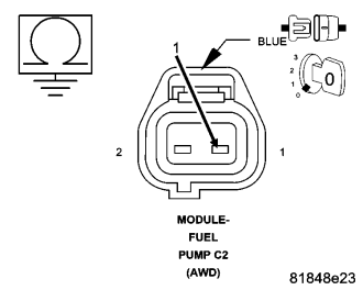
Turn the ignition off.
Measure the resistance between ground and the (Z965) Ground circuit in the Fuel Pump Module harness connector.
Is the resistance below 5 ohms?
Yes
- Go to 7
No
- Repair the (Z965) Ground for an open circuit or high resistance.
- Perform the Body Verification Test Ver. 1 (Refer to 8 - ELECTRICAL/ELECTRONIC CONTROL MODULES)
7. FUEL TANK WIRING HARNESS INSPECTION
WARNING: The fuel system is under a constant pressure (even with the engine off). Before testing or servicing any fuel system hose, fitting or line, the fuel system pressure must be released. Failure to follow these instructions can result in personal injury or death.
Remove the fuel tank in accordance with the Service Information.
Inspect the wiring and connectors between the Fuel Pump Module harness connector and both Fuel Level Sensors.
Look for any chafed, pierced, pinched, or partially broken wires.
Look for broken, bent, pushed out or corroded terminals.
Were any problems found?
Yes
- Repair as necessary.
- Perform the Body Verification Test Ver. 1 (Refer to 8 - ELECTRICAL/ELECTRONIC CONTROL MODULES)
No
- Go to 8
8. FUEL LEVEL SENSOR 1 INSPECTION
Remove the Fuel Level Sensor 1.
Inspect the Fuel Level Sensor 1 and the inside of the fuel tank for any condition that would restrict the movement of the fuel level sensor float.
Were any problems found?
Yes
- Repair or replace the fuel tank components as necessary.
- Perform the Body Verification Test Ver. 1 (Refer to 8 - ELECTRICAL/ELECTRONIC CONTROL MODULES)
No
- Go to 9
9. FUEL LEVEL SENSOR 1 RESISTANCE
Move the Fuel Level Sensor 1 float to its lowest point of travel.
Measure the resistance between the terminals of Fuel Level Sensor 1.
NOTE: The resistance should be approximately 220 ohms with the float at its lowest point of travel (empty).
Move the Fuel Level Sensor 1 float to its highest point of travel.
Measure the resistance between the terminals of Fuel Level Sensor 1.
NOTE: The resistance should be approximately 20 ohms with the float at its highest point of travel (full).
Is the resistance of the sensor within the values described above?
Yes
- Go to 10
No
- Replace the Fuel Level Sensor 2.
- Perform the Body Verification Test Ver. 1 (Refer to 8 - ELECTRICAL/ELECTRONIC CONTROL MODULES)
10. FUEL LEVEL SENSOR 2 INSPECTION
Remove the Fuel Level Sensor 2 sensor.
Inspect the Fuel Level Sensor 2 and the inside of the fuel tank for any condition that would restrict the movement of the fuel level sensor float.
Were any problems found?
Yes
- Repair or replace the fuel tank components as necessary.
- Perform the Body Verification Test Ver. 1 (Refer to 8 - ELECTRICAL/ELECTRONIC CONTROL MODULES)
No
- Replace the Fuel Level Sensor 2.
- Perform the Body Verification Test Ver. 1 (Refer to 8 - ELECTRICAL/ELECTRONIC CONTROL MODULES)
11. (N5) FUEL LEVEL SIGNAL 2 CIRCUIT SHORTED TO VOLTAGE
Turn the ignition off.
Disconnect the Instrument Cluster (CCN) connector.
Turn the ignition on.
Measure the voltage of the (N5) Fuel Level Signal 2 circuit in the Fuel Level Sensor 2 harness connector.
Is there any voltage present?
Yes
- Repair the (N5) Fuel Level Signal 2 circuit for a short to voltage.
- Perform the Body Verification Test Ver. 1 (Refer to 8 - ELECTRICAL/ELECTRONIC CONTROL MODULES)
No
- Go to 12
12. (N5) FUEL LEVEL SIGNAL 2 CIRCUIT SHORTED TO GROUND
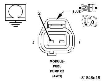
Turn the ignition off.
Measure the resistance between ground and the (N5) Fuel Level Signal 2 circuit in the Fuel Level Sensor 2 harness connector.
Is the resistance above 100 ohms?
Yes
- Go to 13
No
- Repair the (N5) Fuel Level Signal 2 circuit for a short to ground.
- Perform the Body Verification Test Ver. 1 (Refer to 8 - ELECTRICAL/ELECTRONIC CONTROL MODULES)
13. (N5) FUEL LEVEL SIGNAL 2 CIRCUIT OPEN OR HIGH RESISTANCE
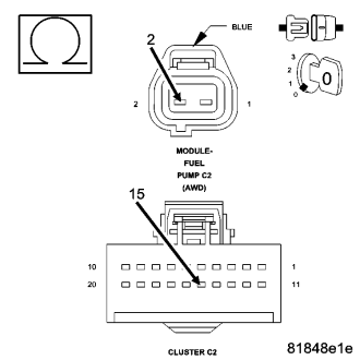
Measure the resistance of the (N5) Fuel Level Signal 2 circuit between the Fuel Level Sensor 2 harness connector and the Instrument Cluster (CCN) harness connector.
Is the resistance below 5.0 ohms?
Yes
- Go to 17
No
- Repair the (N5) Fuel Level Signal 2 circuit for an open circuit or high resistance.
- Perform the Body Verification Test Ver. 1 (Refer to 8 - ELECTRICAL/ELECTRONIC CONTROL MODULES)
14. (N4) FUEL LEVEL SIGNAL 1 CIRCUIT SHORTED TO VOLTAGE
Turn the ignition off.
Disconnect the Instrument Cluster (CCN) connector.
Turn the ignition on.
Measure the voltage of the (N4) Fuel Level Signal 1 circuit in the Fuel Level Sensor 1 harness connector.
Is there any voltage present?
Yes
- Repair the (N4) Fuel Level Signal 1 circuit for a short to voltage.
- Perform the Body Verification Test Ver. 1 (Refer to 8 - ELECTRICAL/ELECTRONIC CONTROL MODULES)
No
- Go to 15
15. (N4) FUEL LEVEL SIGNAL 1 CIRCUIT SHORTED TO GROUND
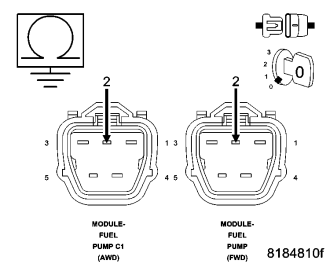
Turn the ignition off.
Measure the resistance between ground and the (N4) Fuel Level Signal 1 circuit in the Fuel Level Sensor 1 harness connector.
Is the resistance above 100 ohms?
Yes
- Go to 16
No
- Repair the (N4) Fuel Level Signal 1 circuit for a short to ground.
- Perform the Body Verification Test Ver. 1 (Refer to 8 - ELECTRICAL/ELECTRONIC CONTROL MODULES)
16. (N4) FUEL LEVEL SIGNAL 1 CIRCUIT OPEN OR HIGH RESISTANCE
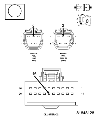
Measure the resistance of the (N4) Fuel Level Signal 1 circuit between the Fuel Level Sensor 1 harness connector and the Instrument Cluster (CCN) harness connector.
Is the resistance below 5.0 ohms?
Yes
- Go to 17
No
- Repair the (N4) Fuel Level Signal 1 circuit for an open circuit or high resistance.
- Perform the Body Verification Test Ver. 1 (Refer to 8 - ELECTRICAL/ELECTRONIC CONTROL MODULES)
17. INSTRUMENT CLUSTER (CCN)
Using the wiring diagram/schematic as a guide, inspect the wiring and connectors between the Fuel Pump Module and the Instrument Cluster (CCN).
Look for any chafed, pierced, pinched, or partially broken wires.
Look for broken, bent, pushed out or corroded terminals.
Refer to any Technical Service Bulletins that may apply.
Were any problems found?
Yes
- Repair as necessary.
- Perform the Body Verification Test Ver. 1 (Refer to 8 - ELECTRICAL/ELECTRONIC CONTROL MODULES)
No
- Replace the Instrument Cluster (CCN) in accordance with the Service Information.
- Perform the Body Verification Test Ver. 1 (Refer to 8 - ELECTRICAL/ELECTRONIC CONTROL MODULES)