SPECIFICATIONS
SPECIFICATIONS - FRAME DIMENSIONS
Frame dimensions are listed in metric scale. All dimensions are from center to center of Principal Locating Point (PLP), or from center to center of PLP and fastener location.
VEHICLE PREPARATION
Position the vehicle on a level work surface. Using screw or bottle jacks, adjust the vehicle PLP heights to the specified dimension above a level work surface. Vertical dimensions can be taken from the work surface to the locations indicated were applicable.
| DESCRIPTION |
FIGURE |
| FRAME DIMENSIONS - PLAN VIEW |
FRAME DIMENSIONS - PLAN VIEW |
| FRAME DIMENSIONS - SIDE VIEW |
FRAME DIMENSIONS - SIDE VIEW |
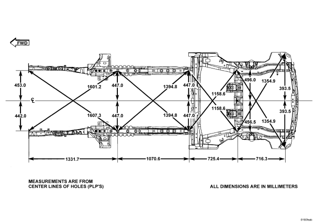
| FRAME DIMENSIONS - PLAN VIEW |
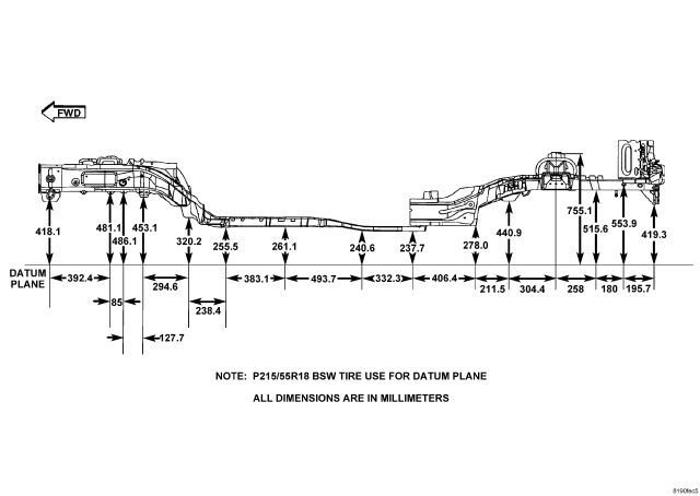
| FRAME DIMENSIONS - SIDE VIEW |
TORQUE
DESCRIPTION |
N·m |
Ft. Lbs. |
In. Lbs. |
| Ball joint stud pinch bolt |
82 |
60 |
— |
| Brake Flex Hose Trailing Link Mounting Nut |
15 |
11 |
— |
| Brake flex hose trailing link mounting screw |
23 |
17 |
— |
| Control arm bushing bolts |
123 |
91 |
— |
| Cradle bolts front, rear, inboard and outboard |
110 |
81 |
— |
| Crossmember Mounting Bolts |
153 |
112 |
— |
| Crossmember rear roll mount through bolt |
65 |
48 |
— |
| Engine Anti Roll Bolt. |
65 |
48 |
— |
| Engine cradle bolts |
190 |
140 |
— |
| Front control arm bushing bolts |
123 |
92 |
— |
| Front Fore/aft inboard and outboard crossmember bolts |
78 |
58 |
— |
| Front Fore/aft rearward crossmember bolt |
129 |
95 |
— |
| Hub nut |
244 |
180 |
— |
| Lower control arm front pivot bolts |
163 |
120 |
— |
| Lower control arm rear isolator bushings |
250 |
180 |
— |
| Lower Control Arm Trailing Link Bolt Nut |
95 |
70 |
— |
| Lower link bolts at cradle |
90 |
70 |
— |
| Lower strut bolts |
99 |
73 |
— |
| Pencil nut struts |
58 |
43 |
— |
| Power steering line brackets |
8 |
— |
70 |
| Rear Fore/aft cross member bolts |
129 |
95 |
— |
| Rear half shaft nuts |
244 |
180 |
— |
| Rear roll mount rearward crossmember bolts |
153 |
112 |
— |
| Stabilizer bar bushing bolts |
61 |
45 |
— |
| Stabilizer bar cushion retainer |
28 |
20 |
— |
| Stabilizer bar link nuts |
58 |
430 |
— |
| Steering gear mounting bolts |
61 |
45 |
— |
| Toe link cam bolts |
35 |
26 |
— |
| Trailing link bushing bolts |
110 |
81 |
— |
| Upper Control Arm Trailing Link Bolt Nut |
95 |
70 |
— |
| Upper link bolts at cradle |
90 |
70 |
— |
WELD PROCESS
CAUTION: All welds should conform to DaimlerChrysler vehicle engineering process standard “PS 9472”.
| WELDING PROCESS |
*FLUX CORED ARC |
GAS METAL (MIG) ARC |
SHIELDED METAL ARC (STICK) |
||
| Material Thickness |
1.80 mm |
1.80 mm |
1.80 mm |
1.80 mm |
|
| Electrode Type |
Lincoln Electric Co. Product No. NP-211 MP |
Lincoln Electric Co. Product No. NP-211 MP (Do Not Substitute) |
AWS ER70S-3 (Do Not Substitute) |
AWS E 7018 |
|
| Electrodes Size Inches |
.035 Tubular |
.045 Tubular |
.035 Solid |
3/32 |
|
| Polarity |
3/8” |
3/8” - 1/2” |
1/2” - 5/8” |
N/A |
|
| Shielding Gas |
Electrode “-” Work Piece “+” |
Electrode “-” Work Piece “+” |
Electrode “+” Work Piece “-” |
Electrode “+” Work Piece “-” |
|
| Gas Flow Rate |
N/A |
N/A |
75% Ar 25 - 35 CFH |
N/A |
|
| Wire Feed Speed (inches per minute) |
90 - 110 Vertical Down 60 - 70 Flat & Horizontal |
110 - 130 Vertical Down 70 - 90 Flat & Overhead |
245 - 250 Vertical Down 210 - 225 Flat & Overhead |
N/A |
|
| Approximate Amperage |
|||||
| Vertical |
110 - 120 |
160 - 170 |
175 |
85 (3/32 Dia.) |
|
| Flat & Overhead |
50 - 60 |
120 - 140 |
155 |
90 (3/32 Dia.) |
|
| Voltage |
15 - 16 |
15 - 18 |
19 - 20 |
||
| Direction of Welding |
|||||
| Vertical |
Vertical Down Hill (only) |
Vertical Down Hill (only) |
Vertical Down Hill (only) |
Vertical Up Hill (only) |
|
| Flat & Overhead |
Flat - Push or Drag |
Flat - Push or Drag |
Flat - Push or Drag |
Flat - Drag |
|
*First choice - Flux Cored Arc Welding Process: Butt joints - Vertical position welds - maintain end of electrode wire at leading edge of weld puddle while traveling down hill to produce maximum penetration into sleeve. This technique works for Gas Metal Arc (MIG) as well.
NOTE: If MIG welding process is selected the galvannealed coating must be removed from both sides of the material adjacent to the weld joint.