HALF SHAFT-FRONT
DESCRIPTION
Naturally aspirated models equipped with either an automatic or manual transmission use an unequal-length halfshaft system. The system incorporates two halfshaft assemblies (left and right) that consist of an inner and outer constant velocity (CV) joint and a solid interconnecting shaft. The right halfshaft is longer than the left due to transaxle packaging and powertrain design. Manual transmission models use equal length halfshafts.
Both halfshaft assemblies use the same type of inner and outer joints. The inner joint of both halfshaft assemblies is a tripod joint, and the outer joint of both halfshaft assemblies is a Rzeppa joint. Both tripod joints and Rzeppa joints are true constant velocity (CV) joint assemblies. The inner tripod joint allows for the changes in halfshaft length through the jounce and rebound travel of the front suspension.
| Halfshaft Retaining Hardware |
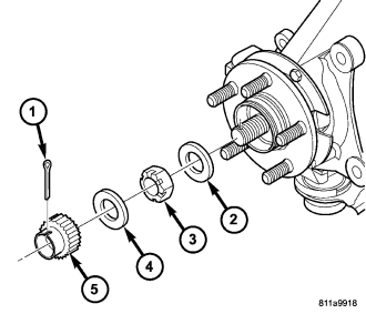
The left halfshaft inner tripod joint and the intermediate shaft are both splined into the transaxle side gears. The inner tripod joints are retained using a snap ring located in the stub shaft of the tripod joint. The outer CV joint has a stub shaft that is splined into the wheel hub and retained by a hub nut (3) and washer (2), nut lock (5), spring washer (4) and cotter pin (1).
OPERATION
Halfshaft assemblies are designed to transmit power from the transaxle to the front wheels, while allowing for powertrain and suspension flex.
REMOVAL
CAUTION: Boot sealing is vital to retain special lubricants and to prevent foreign contaminants from entering the CV joint. Mishandling, such as allowing the assemblies to dangle unsupported, or pulling or pushing the ends can cut boots or damage CV joints. During removal and installation procedures, always support both ends of the halfshaft to prevent damage.
CAUTION: The halfshaft, when installed, acts as a bolt and secures the front hub/bearing assembly. If vehicle is to be supported or moved on its wheels with a halfshaft removed, install a PROPER–SIZED BOLT AND NUT through front hub. Tighten bolt and nut to 244 N·m (180 ft. lbs.). This will ensure that the hub bearing cannot loosen.
1. Disconnect battery negative cable.
2. Place transaxle in gated park.
3. Raise vehicle on hoist.
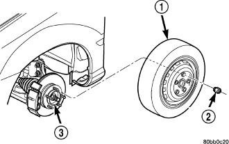
4. Remove wheel and tire assembly (1).
| Halfshaft Retaining Hardware |
5. Remove the cotter pin (1), nut lock (5), spring washer (4), and hub nut (3) from the end of the outer C/V joint stub axle.
6. If equipped with ABS, disconnect the front wheel speed sensor and secure harness out of the way.
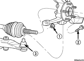
7. Remove nut and bolt (1,2) retaining ball joint stud (3) into steering knuckle.
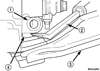
NOTE: Use caution when separating ball joint stud from steering knuckle, so ball joint seal does not get damaged.
8. Separate ball joint stud (4) from steering knuckle (1) by prying down on lower control arm (3).
NOTE: Care must be taken not to separate the inner CV joint during this operation. Do not allow halfshaft to hang by inner CV joint, halfshaft must be supported.
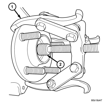
9. Remove halfshaft (2) from steering knuckle by pulling outward on knuckle while pressing in on halfshaft. Support outer end of halfshaft assembly. If difficulty in separating halfshaft from hub is encountered, do not strike shaft with hammer, instead use Puller 1026 (1) to separate.
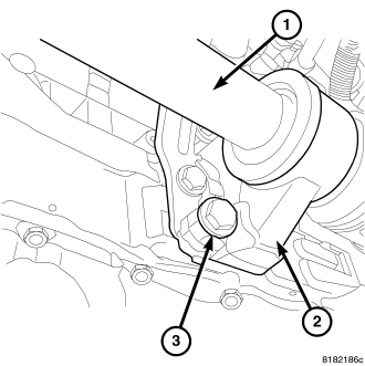
10. Two wheel drive vehicles, remove halfshaft bracket (2) from engine lower mounting bolt (3).
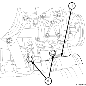
11. Two wheel drive vehicles, remove halfshaft bracket from engine upper mounting bolts (2).
12. Support outer end of the halfshaft assembly.
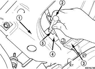
NOTE: Removal of the inner tripod joints is made easier if you apply outward pressure on the joint as you strike the punch with a hammer. Do not pull on interconnecting shaft to remove, as the inner joint will become separated.
13. Remove the inner tripod joints (4) from the side gears of the transaxle using a punch (2) to dislodge the inner tripod joint retaining ring from the transaxle side gear. If removing the right side inner tripod joint, position the punch to the inner tripod joint extraction groove (5) (if equipped). Strike the punch sharply with a hammer to dislodge the right inner joint from the side gear. If removing the left side inner tripod joint, position the punch to the inner tripod joint extraction groove. Strike the punch sharply with a hammer to dislodge the left inner tripod joint from the side gear.
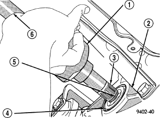
14. Hold inner tripod joint (1) and interconnecting shaft (6) of halfshaft assembly. Remove inner tripod joint from transaxle by pulling it straight out of transaxle side gear and transaxle oil seal (4). When removing tripod joint, do not let spline or snap ring drag across sealing lip of the transaxle to tripod joint oil seal. When tripod joint is removed from transaxle, some fluid will leak out.
CAUTION: The halfshaft, when installed, acts as a bolt and secures the front hub/bearing assembly. If vehicle is to be supported or moved on its wheels with a halfshaft removed, install a PROPER–SIZED BOLT AND NUT through front hub. Tighten bolt and nut to 244 N·m (180 ft. lbs.). This will ensure that the hub bearing cannot loosen.
INSTALLATION
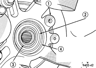
1. Clean all debris and moisture out of steering knuckle (4).
CAUTION: Boot sealing is vital to retain special lubricants and to prevent foreign contaminants from entering the CV joint. Mishandling, such as allowing the assemblies to dangle unsupported, or pulling or pushing the ends can cut boots or damage CV joints. During removal and installation procedures, always support both ends of the halfshaft to prevent damage.
2. Thoroughly clean spline and oil seal sealing surface on tripod joint. Lightly lubricate oil seal sealing surface on tripod joint with fresh clean transmission lubricant.
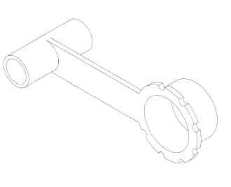
| Protector, 9099 |
NOTE: Always use Seal Protector 9099 when installing half shaft into the transaxle.
3. Holding halfshaft assembly by tripod joint and interconnecting shaft, install tripod joint into transaxle side gear as far as possible by hand.
4. Carefully align tripod joint with transaxle side gears. Then grasp halfshaft interconnecting shaft and push tripod joint into transaxle side gear until fully seated. Test that snap ring is fully engaged with side gear by attempting to remove tripod joint from transaxle by hand. If snap ring is fully engaged with side gear, tripod joint will not be removable by hand.
5. Two wheel drive vehicles install halfshaft bracket (2) to engine lower mounting bolt (3) and tighten bolt to 75 N·m (55 ft. lbs.).
6. Two wheel drive vehicles install halfshaft bracket upper mounting bolts (2) and tighten to 75 N·m (55 ft. lbs.).
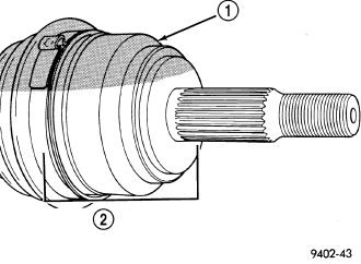
7. Ensure that front of outer CV joint (2) which fits into steering knuckle, is free of debris and moisture before assembling into steering knuckle.
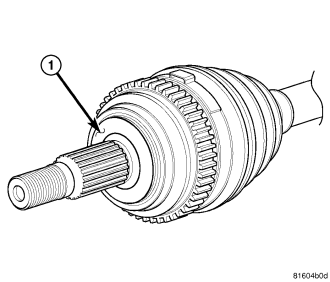
8. Apply a light coating of MOPAR® multi-purpose wheel bearing grease around the circumference of the flat surface (1). Do not apply too much grease, which could spill onto the non-mating and adversely affect the function of the halfshaft.
9. Wipe the rear of the hub and bearing in the knuckle clean where they contact the C/V joint.
10. Install halfshaft back into front hub.
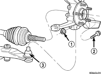
11. Install steering knuckle onto the ball joint stud (3).
NOTE: At this point, the outer joint will not seat completely into the front hub. The outer joint will be pulled into hub and seated when the hub nut is installed and tighten to specification.
12. Install a NEW steering knuckle to ball joint stud bolt (2) and nut (1). Tighten the nut and bolt to 95 N·m (70 ft. lbs.).
| Halfshaft Retaining Hardware |
13. Clean all foreign matter from threads of halfshaft outer stub axle. Install washer (2) and hub nut (3) onto the threads of the stub axle and tighten nut (3) to 244 N·m (180 ft. lbs.).
14. Install spring washer (4), nut lock (5), and cotter pin (1).
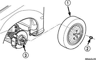
15. Install front wheel and tire assembly (1). Install front wheel lug nuts (2) and tighten to 128 N·m (95 ft. lbs.).
16. Check for correct fluid level in transaxle assembly.
17. Lower vehicle.
18. Connect battery negative cable.