DIAGNOSIS AND TESTING
- B2104-IGNITION RUN/START CONTROL CIRCUIT LOW
- B2105-IGNITION RUN/START CONTROL CIRCUIT HIGH
- B2122-IGNITION RUN CONTROL 1 CIRCUIT LOW
- B212F-IGNITION RUN/ACC CONTROL CIRCUIT LOW
- B2148-IGNITION RUN CONTROL 2 CIRCUIT LOW
- B2184-IGNITION UNLOCK RUN/START CONTROL CIRCUIT LOW
- B2188-IGNITION START CONTROL CIRCUIT LOW
- B218B-IGNITION RUN/START 1 CONTROL CIRCUIT OVERCURRENT
- B218C-IGNITION RUN CONTROL 2 CIRCUIT OVERCURRENT
B2104-IGNITION RUN/START CONTROL CIRCUIT LOW
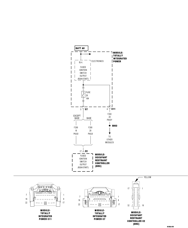
For a complete wiring diagram Refer to Section 8W.
- When Monitored:
With the ignition on.
- Set Condition:
(F200) Fused Ignition Switch Output (Run-Start) circuit low.
| Possible Causes |
| (F200) FUSED IGNITION SWITCH OUTPUT (RUN-START) CIRCUIT SHORT TO GROUND |
| ORC INTERNAL SHORT |
| INTERNALLY SHORTED COMPONENT |
| TIPM |
Diagnostic Test
1. CHECK FOR ACTIVE DTCCheck all fuses.
With the scan tool, read the active DTC's.
Cycle the ignition switch from off to on, leaving the ignition off for a minimum of 30 seconds.
With the scan tool, read the active DTC's.
Does the scan tool display this DTC as active?
Yes
- Go To 2
No
- If the DTC is stored, check for an intermittent condition. Using the wiring diagram/schematic as a guide, visually inspect the related wiring harness connectors. Look for broken, bent, pushed out, or corroded terminals.
2. CHECK (F200) CIRCUIT FOR A SHORT TO GROUND
Remove fuse number 28.
With the scan tool, read DTCs.
Did the DTC changed from active to stored?
Yes
- Go To 3
No
- Go To 5
3. ORC INTERNAL SHORT
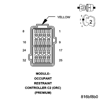
WARNING: To avoid personal injury or death, turn the ignition off, disconnect the battery and wait two minutes before proceeding.
Disconnect the ORC C2 harness connector.
Reinstall fuse number 28.
Turn the ignition on.
Reconnect the battery.
With the scan tool, read DTCs.
Does the scan tool display this DTC as active?
Yes
- Go To 4
No
- Replace the ORC in accordance with the service information.
- Perform BODY VERIFICATION TEST VER 1 (Refer to 8 - ELECTRICAL/ELECTRONIC CONTROL MODULES - STANDARD PROCEDURE)
4. (F200) FUSED IGNITION SWITCH OUTPUT (RUN-START) CIRCUIT SHORT TO GROUND
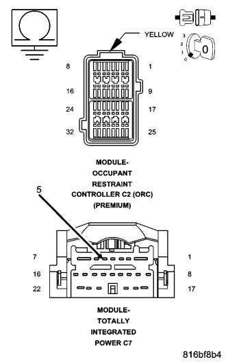
Turn the ignition off.
Disconnect the TIPM C7 harness connector.
Measure the resistance between ground and the (F200) Fused Ignition Switch Output (Run-Start) circuit.
Is the resistance below 10K ohms?
Yes
- Repair the (F200) Fused Ignition Switch Output (Run-Start) circuit for a short to ground.
- Perform BODY VERIFICATION TEST VER 1 (Refer to 8 - ELECTRICAL/ELECTRONIC CONTROL MODULES - STANDARD PROCEDURE)
No
- Repair the TIPM in accordance with the service information.
- Perform BODY VERIFICATION TEST VER 1 (Refer to 8 - ELECTRICAL/ELECTRONIC CONTROL MODULES - STANDARD PROCEDURE)
5. CHECK TIPM FOR AN INTERNAL SHORT
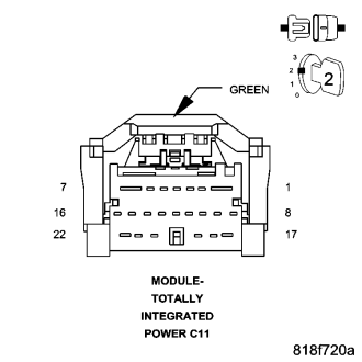
Turn the ignition off.
Disconnect the TIPM C11 harness connector.
With the scan tool, read DTCs.
Did the DTC changed form active to stored?
Yes
- Go To 6
No
- Replace the TIPM in accordance with the service information.
- Perform BODY VERIFICATION TEST VER 1 (Refer to 8 - ELECTRICAL/ELECTRONIC CONTROL MODULES - STANDARD PROCEDURE)
6. CHECK COMPONENT FOR AN INTERNAL SHORT
NOTE: The (F202) circuit is the power supply for multiple modules.
Turn the ignition off.
Reconnect the TIPM C11 harness connector.
Using the wiring diagrams as a guide, disconnect each component that is fed by the (F202) circuit one at a time while checking for the DTC to become stored.
With the scan tool, read DTCs.
Did the DTC changed from active to stored?
Yes
- Replace the shorted component in accordance with the service information.
- Perform BODY VERIFICATION TEST VER 1 (Refer to 8 - ELECTRICAL/ELECTRONIC CONTROL MODULES - STANDARD PROCEDURE)
No
- Repair the (F202) Fused Ignition Switch Output (Run-Start) circuit for a short to ground.
- Perform BODY VERIFICATION TEST VER 1 (Refer to 8 - ELECTRICAL/ELECTRONIC CONTROL MODULES - STANDARD PROCEDURE)
B2105-IGNITION RUN/START CONTROL CIRCUIT HIGH
For a complete wiring diagram Refer to Section 8W.
- When Monitored:
With the ignition on.
- Set Condition:
(F200) Fused Ignition Switch Output (Run-Start) circuit high.
| Possible Causes |
| (F200) FUSED IGNITION SWITCH OUTPUT (RUN-START) CIRCUIT SHORT TO VOLTAGE |
| (F202) FUSED IGNITION SWITCH OUTPUT (RUN-START) CIRCUIT SHORT TO VOLTAGE |
| ORC |
| TIPM |
Diagnostic Test
1. CHECK FOR ACTIVE DTCWith the scan tool, read the active DTC's.
Cycle the ignition switch from off to on, leaving the ignition off for a minimum of 30 seconds.
With the scan tool, read the active DTC's.
Does the scan tool display this DTC as active?
Yes
- Go To 2
No
- If the DTC is stored, check for an intermittent condition. Using the wiring diagram/schematic as a guide, visually inspect the related wiring harness connectors. Look for broken, bent, pushed out, or corroded terminals.
2. ORC INTERNAL SHORT TO VOLTAGE
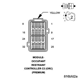
WARNING: To avoid personal injury or death, turn the ignition off, disconnect the battery and wait two minutes before proceeding.
Disconnect the ORC C2 harness connector.
Turn the ignition on.
Reconnect the battery.
With the scan tool, read DTCs.
Does the scan tool display this DTC as active?
Yes
- Go To 3
No
- Replace the ORC in accordance with the service information.
- Perform BODY VERIFICATION TEST VER 1 (Refer to 8 - ELECTRICAL/ELECTRONIC CONTROL MODULES - STANDARD PROCEDURE)
3. (F200) FUSED IGNITION SWITCH OUTPUT (RUN-START) CIRCUIT SHORT TO VOLTAGE
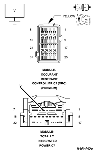
Turn the ignition off.
Disconnect the TIPM C7 harness connector.
Turn the ignition on.
Measure the voltage of the (F200) Fused Ignition Switch Output (Run-Start) circuit.
Is the voltage above 10 volts ?
Yes
- Repair the (F200) Fused Ignition Switch Output (Run-Start) circuit for a short to voltage.
- Perform BODY VERIFICATION TEST VER 1 (Refer to 8 - ELECTRICAL/ELECTRONIC CONTROL MODULES - STANDARD PROCEDURE)
No
- Go To 4
4. (F202) FUSED IGNITION SWITCH OUTPUT (RUN-START) CIRCUIT SHORT TO VOLTAGE
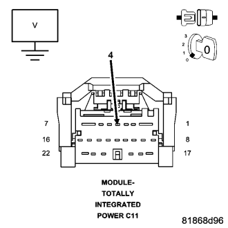
Turn the ignition off.
Disconnect the TIPM C11 harness connector.
Turn the ignition on.
Measure the voltage of the (F202) Fused Ignition Switch Output (Run-Start) circuit.
Is the voltage above 10 volts ?
Yes
- Repair the (F202) Fused Ignition Switch Output (Run-Start) circuit for a short to voltage.
- Perform BODY VERIFICATION TEST VER 1 (Refer to 8 - ELECTRICAL/ELECTRONIC CONTROL MODULES - STANDARD PROCEDURE)
No
- Replace the TIPM in accordance with the service information.
- Perform BODY VERIFICATION TEST VER 1 (Refer to 8 - ELECTRICAL/ELECTRONIC CONTROL MODULES - STANDARD PROCEDURE)
B2122-IGNITION RUN CONTROL 1 CIRCUIT LOW
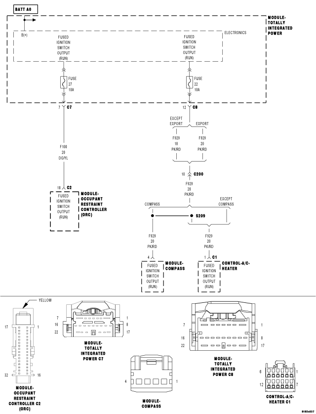
For a complete wiring diagram Refer to Section 8W.
- When Monitored:
With the ignition on.
- Set Condition:
The TIPM detects a short to ground condition on the Fused Ignition Switch Output (RUN).
| Possible Causes |
| SHORT TO GROUND ON (F100) FUSED IGNITION SWITCH OUTPUT (RUN) CIRCUIT |
| SHORT TO GROUND ON (F929) FUSED IGNITION SWITCH OUTPUT (RUN) CIRCUIT |
| A/C HEATER CONTROL |
| COMPASS MODULE |
| ORC |
| TIPM |
Diagnostic Test
1. CHECK FOR ACTIVE DTCCheck all fuses. If any fuses are open, diagnose the appropriate circuit.
With the scan tool, read the DTC's.
Cycle the ignition switch from off to on, leaving the ignition on for a minimum of 10 seconds.
With the scan tool, read the DTC's.
Does the scan tool display this DTC as active?
Yes
- Go To 2
No
- If the DTC is stored, check for an intermittent condition. Using the wiring diagram/schematic as a guide, visually inspect the related wiring harness connectors. Look for broken, bent, pushed out, or corroded terminals.
2. CHECK FOR SHORT TO GROUND ON (F100) FUSED IGNITION SWITCH OUTPUT (RUN) CIRCUIT
Turn the ignition off.
Remove fuse number 27.
Turn the ignition on.
With the scan tool, read the DTC's.
Does the scan tool display this DTC as active?
Yes
- Go To 5
No
- Go To 3
3. CHECK ORC FOR A SHORT TO GROUND
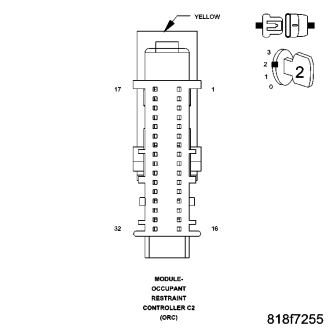
WARNING: To avoid personal injury or death, turn the ignition off, disconnect the battery and wait two minutes before proceeding.
Turn the ignition off.
Disconnect the ORC harness connector.
Reinstall fuse number 27.
Turn the ignition on.
With the scan tool, read the DTC's.
Does the scan tool display this DTC as active?
Yes
- Go To 4
No
- Replace the ORC in accordance with the service information.
- Perform BODY VERIFICATION TEST VER 1 (Refer to 8 - ELECTRICAL/ELECTRONIC CONTROL MODULES - STANDARD PROCEDURE)
4. CHECK FOR SHORT TO GROUND ON (F100) FUSED IGNITION SWITCH OUTPUT (RUN) CIRCUIT
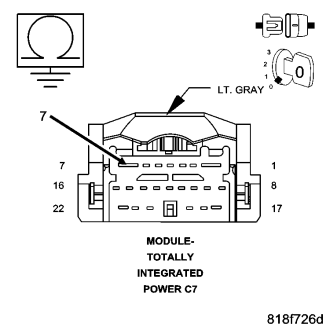
Turn the ignition off.
Disconnect the TIPM C7 harness connector.
Measure the resistance between the (F100) Fused Ignition Switch Output (Run) circuit and ground.
Is the resistance below 10K ohms?
Yes
- Repair the (F100) Fused Ignition Switch Output (Run) circuit for a short to ground.
- Perform BODY VERIFICATION TEST VER 1 (Refer to 8 - ELECTRICAL/ELECTRONIC CONTROL MODULES - STANDARD PROCEDURE)
No
- Test complete.
5. CHECK FOR SHORT TO GROUND ON (F929) FUSED IGNITION SWITCH OUTPUT (RUN) CIRCUIT
Turn the ignition off.
Remove fuse number 22.
Turn the ignition on.
With the scan tool, read the DTC's.
Does the scan tool display this DTC as active?
Yes
- Replace the TIPM in accordance with the service information.
- Perform BODY VERIFICATION TEST VER 1 (Refer to 8 - ELECTRICAL/ELECTRONIC CONTROL MODULES - STANDARD PROCEDURE)
No
- Go To 6
6. CHECK THE A/C HEATER CONTROL FOR A SHORT TO GROUND
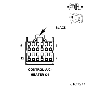
Turn the ignition off.
Disconnect the A/C Heater Control harness connector.
Reinstall fuse number 22.
Turn the ignition on.
With the scan tool, read the DTC's.
Does the scan tool display this DTC as active?
Yes
- Go To 7
No
- Replace the A/C Heater Control in accordance with the service information.
- Perform BODY VERIFICATION TEST VER 1 (Refer to 8 - ELECTRICAL/ELECTRONIC CONTROL MODULES - STANDARD PROCEDURE)
7. CHECK COMPASS MODULE FOR A SHORT TO GROUND
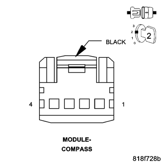
Turn the ignition off.
Disconnect the Compass Module harness connector.
Turn the ignition on.
With the scan tool, read the DTC's.
Does the scan tool display this DTC as active?
Yes
- Go To 8
No
- Replace the Compass Module in accordance with the service information.
- Perform BODY VERIFICATION TEST VER 1 (Refer to 8 - ELECTRICAL/ELECTRONIC CONTROL MODULES - STANDARD PROCEDURE)
8. CHECK FOR SHORT TO GROUND ON (F929) FUSED IGNITION SWITCH OUTPUT (RUN) CIRCUIT
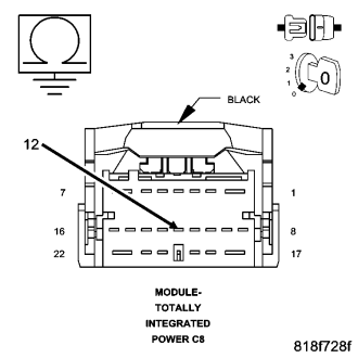
Turn the ignition off.
Disconnect the TIPM C8 harness connector.
Measure the resistance between the (F929) Fused Ignition Switch Output (Run) circuit and ground.
Is the resistance below 10K ohms?
Yes
- Repair the (F929) Fused Ignition Switch Output (Run) circuit for a short to ground.
- Perform BODY VERIFICATION TEST VER 1 (Refer to 8 - ELECTRICAL/ELECTRONIC CONTROL MODULES - STANDARD PROCEDURE)
No
- Replace the TIPM in accordance with the service information.
- Perform BODY VERIFICATION TEST VER 1 (Refer to 8 - ELECTRICAL/ELECTRONIC CONTROL MODULES - STANDARD PROCEDURE)
B212F-IGNITION RUN/ACC CONTROL CIRCUIT LOW
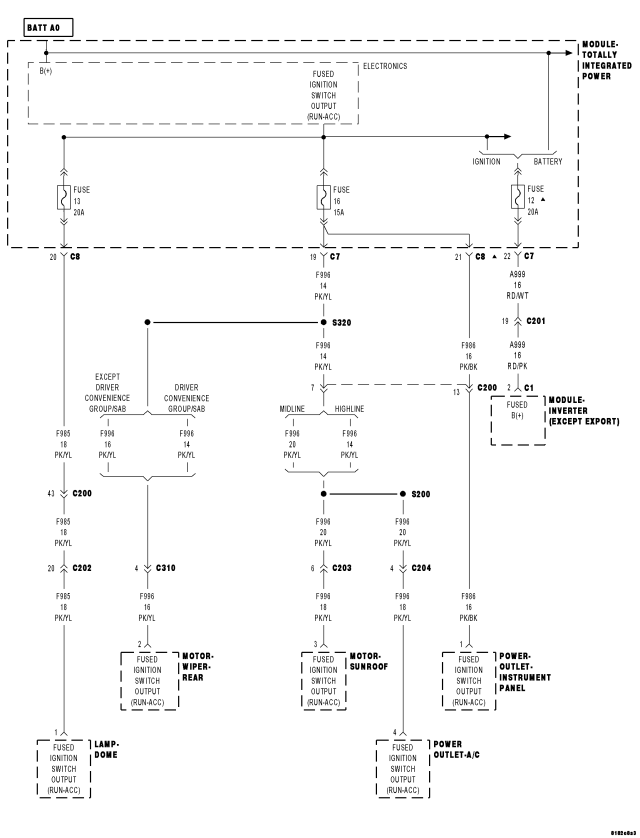
For a complete wiring diagram Refer to Section 8W.
- When Monitored:
With the ignition on.
- Set Condition:
The TIPM detects a short to ground condition on the Fused Ignition Switch Output (RUN/ACC) circuit.
| Possible Causes |
| SHORT TO GROUND ON THE (F996) FUSED IGNITION SWITCH OUTPUT (RUN/ACC) CIRCUIT |
| SHORT TO GROUND ON THE (F985) FUSED IGNITION SWITCH OUTPUT (RUN/ACC) CIRCUIT |
| SHORT TO GROUND ON THE (A999) FUSED IGNITION SWITCH OUTPUT (RUN/ACC) CIRCUIT |
| SUNROOF MOTOR |
| A/C POWER OUTLET |
| REAR WIPER MOTOR |
| DOME LAMP |
| INVERTER MODULE |
| TIPM |
Diagnostic Test
1. CHECK FOR ACTIVE DTCCheck all fuses.
With the scan tool, read the DTC's.
Cycle the ignition switch from off to on, leaving the ignition on for a minimum of 10 seconds.
With the scan tool, read the DTC's.
Does the scan tool display this DTC as active?
Yes
- Go To 2
- Perform BODY VERIFICATION TEST VER 1 (Refer to 8 - ELECTRICAL/ELECTRONIC CONTROL MODULES - STANDARD PROCEDURE)
No
- If the DTC is stored, check for an intermittent condition. Using the wiring diagram/schematic as a guide, visually inspect the related wiring harness connectors. Look for broken, bent, pushed out, or corroded terminals.
2. CHECK TIPM FOR AN INTERNAL SHORT TO GROUND
Turn the ignition off.
Remove fuses 13, 16, and 12.
Turn the ignition on.
With the scan tool, read the DTC's.
Does the scan tool display this DTC as active?
Yes
- Replace the TIPM in accordance with the service information.
- Perform BODY VERIFICATION TEST VER 1 (Refer to 8 - ELECTRICAL/ELECTRONIC CONTROL MODULES - STANDARD PROCEDURE)
No
- Go To 3
3. CHECK FOR SHORT TO GROUND ON THE (F996) FUSED IGNITION SWITCH OUTPUT CIRCUIT
Turn the ignition off.
Reinstall fuses 12, 13, and 16.
Remove fuse number 16.
Turn the ignition on.
With the scan tool, read the DTC's.
Does the scan tool display this DTC as active?
Yes
- Go To 4
No
- Go To 6
4. CHECK FOR SHORT TO GROUND ON THE (F985) FUSED IGNITION SWITCH OUTPUT CIRCUIT
Turn the ignition off.
Remove fuse number 13.
Turn the ignition on.
With the scan tool, read the DTC's.
Does the scan tool display this DTC as active?
Yes
- Go To 5
No
- Go To 9
5. CHECK FOR SHORT TO GROUND ON THE (A999) FUSED IGNITION SWITCH OUTPUT CIRCUIT
Turn the ignition off.
Remove fuse number 12.
Turn the ignition on.
With the scan tool, read the DTC's.
Does the scan tool display this DTC as active?
Yes
- Replace the TIPM in accordance with the service information.
- Perform BODY VERIFICATION TEST VER 1 (Refer to 8 - ELECTRICAL/ELECTRONIC CONTROL MODULES - STANDARD PROCEDURE)
No
- Go To 10
6. CHECK SUNROOF MOTOR FOR A SHORT TO GROUND
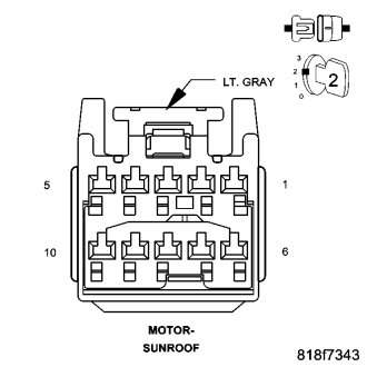
Turn the ignition off.
Disconnect the Sunroof Motor harness connector.
Turn the ignition on.
With the scan tool, read the DTC's.
Does the scan tool display this DTC as active?
Yes
- Go To 7
No
- Replace the Sunroof Motor in accordance with the service information.
- Perform BODY VERIFICATION TEST VER 1 (Refer to 8 - ELECTRICAL/ELECTRONIC CONTROL MODULES - STANDARD PROCEDURE)
7. CHECK A/C POWER OUTLET FOR A SHORT TO GROUND
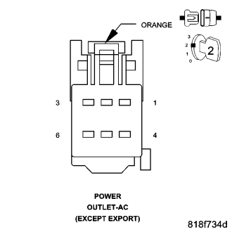
Turn the ignition off.
Disconnect the A/C Power Outlet harness connector.
Turn the ignition on.
With the scan tool, read the DTC's.
Does the scan tool display this DTC as active?
Yes
- Go To 8
No
- Replace the A/C Power Outlet in accordance with the service information.
- Perform BODY VERIFICATION TEST VER 1 (Refer to 8 - ELECTRICAL/ELECTRONIC CONTROL MODULES - STANDARD PROCEDURE)
8. CHECK REAR WIPER MOTOR FOR A SHORT TO GROUND
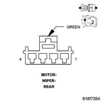
Turn the ignition off.
Disconnect the Rear Wiper Motor harness connector.
Turn the ignition on.
With the scan tool, read the DTC's.
Does the scan tool display this DTC as active?
Yes
- Repair the (F996) Fused Ignition Switch Output (Run-Acc) circuit for a short to ground.
- Perform BODY VERIFICATION TEST VER 1 (Refer to 8 - ELECTRICAL/ELECTRONIC CONTROL MODULES - STANDARD PROCEDURE)
No
- Replace the Rear Wiper Motor in accordance with the service information.
- Perform BODY VERIFICATION TEST VER 1 (Refer to 8 - ELECTRICAL/ELECTRONIC CONTROL MODULES - STANDARD PROCEDURE)
9. CHECK DOME LAMP FOR A SHORT TO GROUND
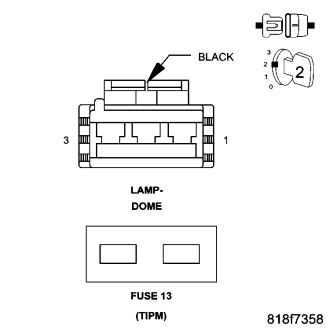
Turn the ignition off.
Reinstall Fuse number 13.
Disconnect the Dome Lamp harness connector.
Turn the ignition on. Activate Dome Lamp.
With the scan tool, read the DTC's.
Does the scan tool display this DTC as active?
Yes
- Repair the (F985) Fused Ignition Switch Output (Run-Acc) circuit for a short to ground.
- Perform BODY VERIFICATION TEST VER 1 (Refer to 8 - ELECTRICAL/ELECTRONIC CONTROL MODULES - STANDARD PROCEDURE)
No
- Replace the Sunroof Motor in accordance with the service information.
- Perform BODY VERIFICATION TEST VER 1 (Refer to 8 - ELECTRICAL/ELECTRONIC CONTROL MODULES - STANDARD PROCEDURE)
10. CHECK INVERTER MODULE FOR A SHORT TO GROUND
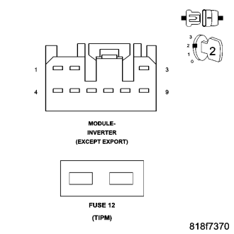
Turn the ignition off.
Reinstall fuse number 12.
Disconnect the Inverter Module harness connector.
Turn the ignition on.
With the scan tool, read the DTC's.
Does the scan tool display this DTC as active?
Yes
- Repair the (A999) Fused B+ circuit for a short to ground.
- Perform BODY VERIFICATION TEST VER 1 (Refer to 8 - ELECTRICAL/ELECTRONIC CONTROL MODULES - STANDARD PROCEDURE)
No
- Replace the Inverter Module in accordance with the service information.
- Perform BODY VERIFICATION TEST VER 1 (Refer to 8 - ELECTRICAL/ELECTRONIC CONTROL MODULES - STANDARD PROCEDURE)
B2148-IGNITION RUN CONTROL 2 CIRCUIT LOW
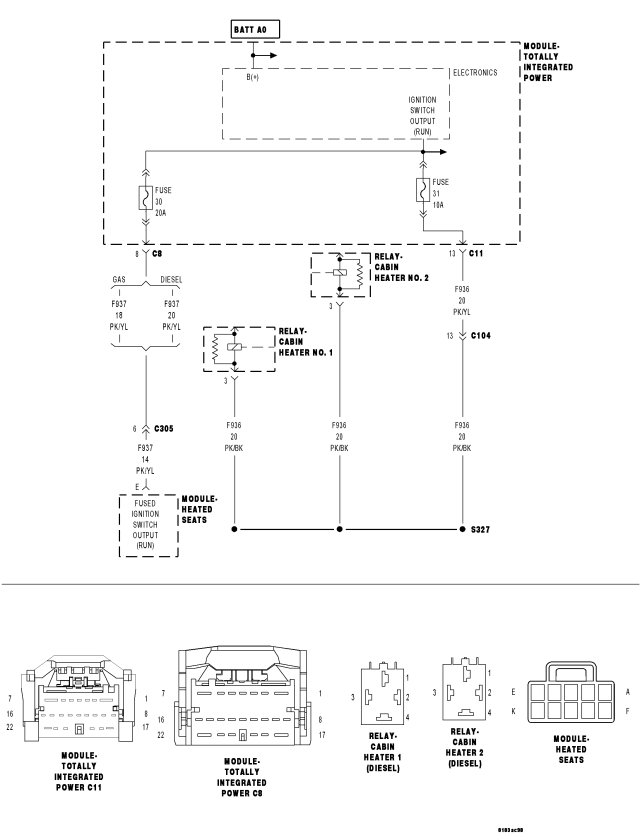
For a complete wiring diagram Refer to Section 8W.
- When Monitored:
With the ignition on.
- Set Condition:
Ignition Run Control 2 Circuit Low.
| Possible Causes |
| (F937) FUSED IGNITION SWITCH OUTPUT (RUN) SHORTED TO GROUND |
| (F936) FUSED IGNITION SWITCH OUTPUT (RUN) SHORTED TO GROUND |
| HEATED SEATS MODULE |
| CABIN HEATER RELAY NUMBER 1 |
| CABIN HEATER RELAY NUMBER 2 |
| TIPM |
Diagnostic Test
1. CHECK FOR ACTIVE DTCCheck all fuses. If any fuses are open, diagnose the appropriate circuit.
With the scan tool, read the DTC's.
Cycle the ignition switch from off to on, leaving the ignition on for a minimum of 10 seconds.
With the scan tool, read the DTC's.
Does the scan tool display this DTC as active?
Yes
- Go To 2
No
- If the DTC is stored, check for an intermittent condition. Using the wiring diagram/schematic as a guide, visually inspect the related wiring harness connectors. Look for broken, bent, pushed out, or corroded terminals.
2. (F937) CIRCUIT SHORT TO GROUND
Remove fuse number 30.
With the scan tool, read the DTC's.
Does the scan tool display this DTC as active?
Yes
- Go To 3
No
- Go To 4
3. (F936) CIRCUIT SHORT TO GROUND
Remove fuse number 31.
With the scan tool, read the DTC's.
Does the scan tool display this DTC as active?
Yes
- Replace the TIPM in accordance with the service information.
- Perform BODY VERIFICATION TEST VER 1 (Refer to 8 - ELECTRICAL/ELECTRONIC CONTROL MODULES - STANDARD PROCEDURE)
No
- Go To 6
4. HEATED SEATS MODULE SHORTED TO GROUND
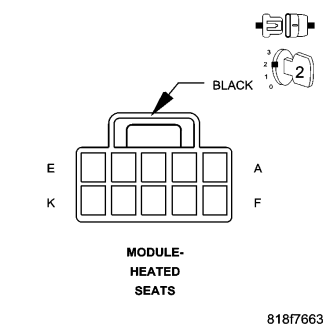
Turn the ignition off.
Disconnect the Heated Seats Module harness connector.
Reinstall fuse number 30.
Turn the ignition on.
With the scan tool, read the DTC's.
Does the scan tool display this DTC as active?
Yes
- Go To 5
No
- Replace the Heated Seats Module in accordance with the service information.
- Perform BODY VERIFICATION TEST VER 1 (Refer to 8 - ELECTRICAL/ELECTRONIC CONTROL MODULES - STANDARD PROCEDURE)
5. (F937) FUSED IGNITION SWITCH OUTPUT (RUN) SHORTED TO GROUND
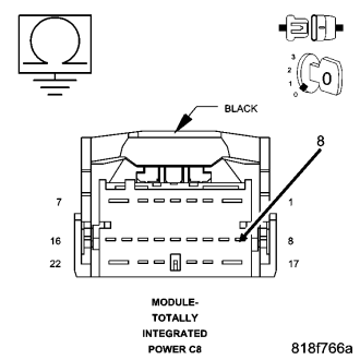
Turn the ignition off.
Disconnect the TIPM C8 harness connector.
Measure the resistance between ground and the (F937) Fused Ignition Switch Output (Run) circuit and ground.
Is the resistance below 10K ohms?
Yes
- Repair the (F937) Fused Ignition Switch Output (Run) circuit for a short to ground.
- Perform BODY VERIFICATION TEST VER 1 (Refer to 8 - ELECTRICAL/ELECTRONIC CONTROL MODULES - STANDARD PROCEDURE)
No
- Replace the TIPM in accordance with the service information.
- Perform BODY VERIFICATION TEST VER 1 (Refer to 8 - ELECTRICAL/ELECTRONIC CONTROL MODULES - STANDARD PROCEDURE)
6. CABIN HEATER RELAY NUMBER 1 SHORTED TO GROUND
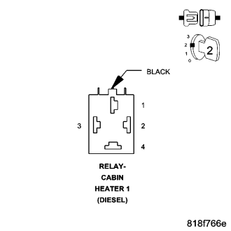
Turn the ignition off.
Disconnect the Cabin Heater Relay Number 1 harness connector.
Reinstall fuse number 31.
Turn the ignition on.
With the scan tool, read the DTC's.
Does the scan tool display this DTC as active?
Yes
- Go To 7
No
- Replace the Cabin Heater Relay Number 1 in accordance with the service information.
- Perform BODY VERIFICATION TEST VER 1 (Refer to 8 - ELECTRICAL/ELECTRONIC CONTROL MODULES - STANDARD PROCEDURE)
7. CABIN HEATER RELAY NUMBER 2 SHORTED TO GROUND
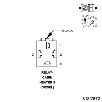
Turn the ignition off.
Disconnect the Cabin Heater Relay Number 2 harness connector.
Turn the ignition on.
With the scan tool, read the DTC's.
Does the scan tool display this DTC as active?
Yes
- Go To 8
No
- Replace the Cabin Heater Relay Number 2 in accordance with the service information.
- Perform BODY VERIFICATION TEST VER 1 (Refer to 8 - ELECTRICAL/ELECTRONIC CONTROL MODULES - STANDARD PROCEDURE)
8. (F936) FUSED IGNITION SWITCH OUTPUT (RUN) SHORTED TO GROUND
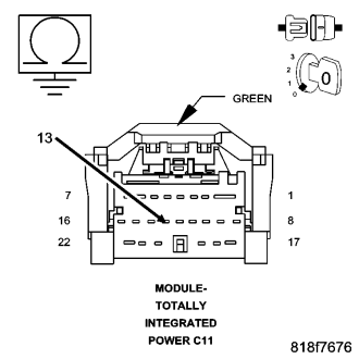
Turn the ignition off.
Disconnect the TIPM C11 harness connector.
Measure the resistance between ground and the (F936) Fused Ignition Switch Output (Run) circuit and ground.
Is the resistance below 10K ohms?
Yes
- Repair the (F936) Fused Ignition Switch Output (Run) circuit for a short to ground.
- Perform BODY VERIFICATION TEST VER 1 (Refer to 8 - ELECTRICAL/ELECTRONIC CONTROL MODULES - STANDARD PROCEDURE)
No
- Replace the TIPM in accordance with the service information.
- Perform BODY VERIFICATION TEST VER 1 (Refer to 8 - ELECTRICAL/ELECTRONIC CONTROL MODULES - STANDARD PROCEDURE)
B2184-IGNITION UNLOCK RUN/START CONTROL CIRCUIT LOW
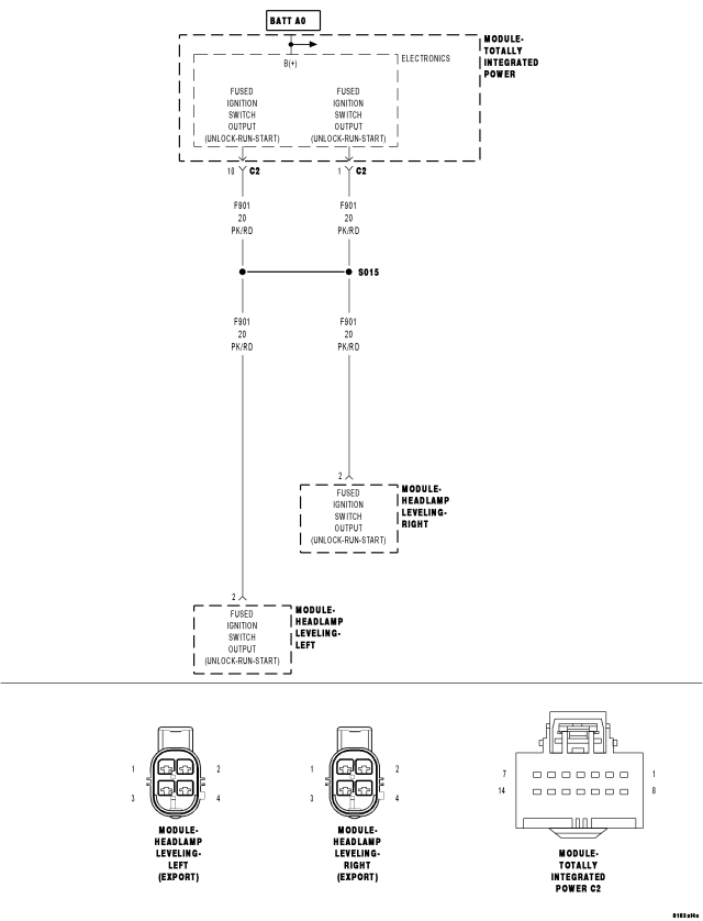
For a complete wiring diagram Refer to Section 8W.
- When Monitored:
With the ignition on.
- Set Condition:
(F901) Fused Ignition Switch Output (Unlock-Run-Start) circuit low.
| Possible Causes |
| (F901) FUSED IGNITION SWITCH OUTPUT (UNLOCK-RUN-START) CIRCUIT SHORT TO GROUND |
| LEFT HEADLAMP LEVELING MODULE |
| RIGHT HEADLAMP LEVELING MODULE |
| TIPM |
Diagnostic Test
1. CHECK FOR ACTIVE DTCWith the scan tool, read the DTC's.
Cycle the ignition switch from off to on, leaving the ignition on for a minimum of 10 seconds.
With the scan tool, read the DTC's.
Does the scan tool display this DTC as active?
Yes
- Go To 2
No
- If the DTC is stored, check for an intermittent condition. Using the wiring diagram/schematic as a guide, visually inspect the related wiring harness connectors. Look for broken, bent, pushed out, or corroded terminals.
2. LEFT HEADLAMP LEVELING MODULE INTERNAL SHORT
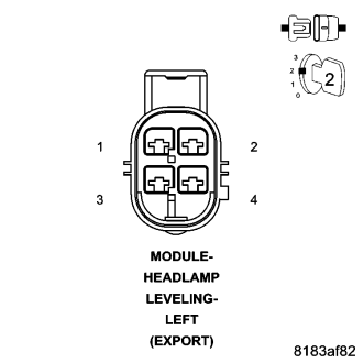
Turn the ignition off.
Disconnect the Left Headlamp Leveling Module harness connector.
Turn the ignition on.
With the scan tool, read DTCs.
Does the scan tool display this DTC as active?
Yes
- Go To 3
No
- Replace the Left Headlamp Leveling Module in accordance with the service information.
- Perform BODY VERIFICATION TEST VER 1 (Refer to 8 - ELECTRICAL/ELECTRONIC CONTROL MODULES - STANDARD PROCEDURE)
3. RIGHT HEADLAMP LEVELING MODULE INTERNAL SHORT
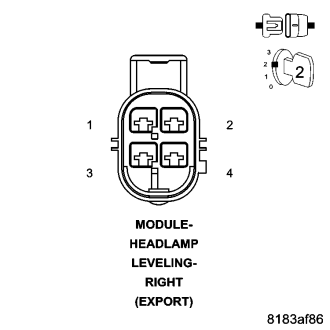
Turn the ignition off.
Disconnect the Right Headlamp Leveling Module harness connector.
Turn the ignition on.
With the scan tool, read DTCs.
Does the scan tool display this DTC as active?
Yes
- Go To 4
No
- Replace the Right Headlamp Leveling Module in accordance with the service information.
- Perform BODY VERIFICATION TEST VER 1 (Refer to 8 - ELECTRICAL/ELECTRONIC CONTROL MODULES - STANDARD PROCEDURE)
4. (F901) FUSED IGNITION SWITCH OUTPUT (UNLOCK-RUN-START) CIRCUIT SHORT TO GROUND
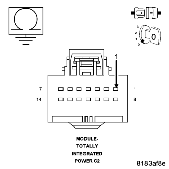
Turn the ignition off.
Disconnect the TIPM C2 harness connector.
Measure the resistance between ground and the (F901) Fused Ignition Switch Output (Unlock-Run-Start) circuit.
Is the resistance below 10K ohms?
Yes
- Repair the (F901) Fused Ignition Switch Output (Unlock-Run-Start) circuit for a short to ground.
- Perform BODY VERIFICATION TEST VER 1 (Refer to 8 - ELECTRICAL/ELECTRONIC CONTROL MODULES - STANDARD PROCEDURE)
No
- Replace the TIPM in accordance with the service information.
- Perform BODY VERIFICATION TEST VER 1 (Refer to 8 - ELECTRICAL/ELECTRONIC CONTROL MODULES - STANDARD PROCEDURE)
B2188-IGNITION START CONTROL CIRCUIT LOW
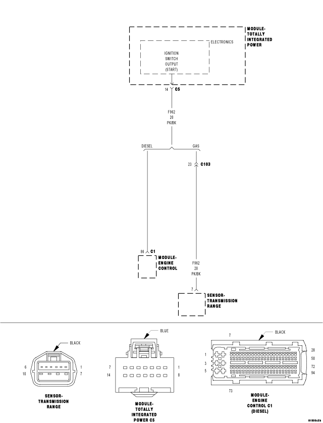
For a complete wiring diagram Refer to Section 8W.
- When Monitored:
With the ignition in the Start position.
- Set Condition:
The TIPM detects a short to ground condition in the (F962) Fused Ignition Switch Output (Start) circuit.
| Possible Causes |
| (F962) FUSED IGNITION SWITCH OUTPUT (START) CIRCUIT SHORT TO GROUND |
| TRANSMISSION RANGE SENSOR |
| TIPM |
Diagnostic Test
1. CHECK FOR ACTIVE DTCWith the scan tool, read the DTC's.
Cycle the ignition switch from off to on, leaving the ignition on for a minimum of 10 seconds.
With the scan tool, read the DTC's.
Does the scan tool display this DTC as active?
Yes
- Go To 2
No
- If the DTC is stored, check for an intermittent condition. Using the wiring diagram/schematic as a guide, visually inspect the related wiring harness connectors. Look for broken, bent, pushed out, or corroded terminals.
2. TRANSMISSION RANGE SENSOR
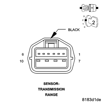
Turn the ignition off.
Disconnect the Transmission Range Sensor harness connector.
Turn the ignition on, wait 30 seconds.
With the scan tool, read TIPM DTCs.
Does the scan tool display this DTC as active?
Yes
- Replace the Transmission Range Sensor in accordance with the service information.
- Perform BODY VERIFICATION TEST VER 1 (Refer to 8 - ELECTRICAL/ELECTRONIC CONTROL MODULES - STANDARD PROCEDURE)
No
- Go To 3
3. ENGINE CONTROL MODULE (DIESEL)
Turn the ignition off.
Disconnect the Diesel ECM C1 harness connector.
Turn the ignition on, wait 30 seconds.
With the scan tool, read TIPM DTCs.
Does the scan tool display this DTC as active?
Yes
- Replace the ECM in accordance with the service information.
- Perform BODY VERIFICATION TEST VER 1 (Refer to 8 - ELECTRICAL/ELECTRONIC CONTROL MODULES - STANDARD PROCEDURE)
No
- Go To 4
4. (F962) FUSED IGNITION SWITCH OUTPUT (START) CIRCUIT SHORT TO GROUND
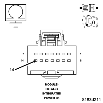
Turn the ignition off.
Disconnect the TIPM C5 connector.
Measure the resistance between the (F962) Fused Ignition Switch Output (START) circuit and ground.
Is the resistance below 10K ohms?
Yes
- Repair the (F962) Fused Ignition Switch Output (START) circuit for a short to ground.
- Perform BODY VERIFICATION TEST VER 1 (Refer to 8 - ELECTRICAL/ELECTRONIC CONTROL MODULES - STANDARD PROCEDURE)
No
- Replace the TIPM in accordance with the service information.
- Perform BODY VERIFICATION TEST VER 1 (Refer to 8 - ELECTRICAL/ELECTRONIC CONTROL MODULES - STANDARD PROCEDURE)
B218B-IGNITION RUN/START 1 CONTROL CIRCUIT OVERCURRENT
For a complete wiring diagram Refer to Section 8W.
- When Monitored:
With the ignition on.
- Set Condition:
Over current condition detected on the Fused Ignition Switch Output (Run-Start) circuit.
| Possible Causes |
| TERMINAL DAMAGE OR CORROSION |
| HIGH RESISTANCE ON THE (F200) FUSED IGNITION SWITCH OUTPUT (RUN-START) CIRCUIT |
| OCCUPANT RESTRAINT CONTROLLER (ORC) |
| TIPM |
Diagnostic Test
1. CHECK FOR ACTIVE DTCWith the scan tool, read the DTC's.
Cycle the ignition switch from off to on, leaving the ignition on for a minimum of 10 seconds.
With the scan tool, read the DTC's.
Does the scan tool display this DTC as active?
Yes
- Go To 2
No
- If the DTC is stored, check for an intermittent condition. Using the wiring diagram/schematic as a guide, visually inspect the related wiring harness connectors. Look for broken, bent, pushed out, or corroded terminals.
2. INSPECT THE TIPM AND ORC TERMINALS AND WIRE HARNESS FOR A CONDITION CAUSING HIGH CIRCUIT RESISTANCE
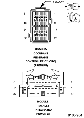
WARNING: To avoid personal injury or death, turn the ignition off, disconnect the battery and wait two minutes before proceeding.
Disconnect the TIPM C7 harness connector.
Disconnect the ORC harness connector.
Inspect the connector terminal for signs of corrosion build up and damage.
Visually inspect the wiring harness for any chafed, pierced, pinched or partially broken wires hidden in the wire insulation.
Were any of the above conditions found?
Yes
- Repair as necessary.
- Perform BODY VERIFICATION TEST VER 1. (Refer to 8 - ELECTRICAL/ELECTRONIC CONTROL MODULES - STANDARD PROCEDURE)
No
- Go To 3
3. INSPECT THE (F202) FUSED IGNITION SWITCH OUTPUT (RUN-START) CIRCUIT FOR A CONDITION CAUSING HIGH CIRCUIT RESISTANCE
Disconnect the TIPM C11 harness connector.
Inspect the connector terminal for signs of corrosion build up and damage.
Using the wiring diagrams, visually inspect the associated wiring harnesses and connectors for any chafed, pierced, pinched or partially broken wires hidden in the wire insulation.
Were any of the above conditions found?
Yes
- Repair as necessary.
- Perform BODY VERIFICATION TEST VER 1. (Refer to 8 - ELECTRICAL/ELECTRONIC CONTROL MODULES - STANDARD PROCEDURE)
No
- Replace the TIPM in accordance with the service information.
- Perform BODY VERIFICATION TEST VER 1. (Refer to 8 - ELECTRICAL/ELECTRONIC CONTROL MODULES - STANDARD PROCEDURE)
B218C-IGNITION RUN CONTROL 2 CIRCUIT OVERCURRENT
For a complete wiring diagram Refer to Section 8W.
- When Monitored:
With the ignition on.
- Set Condition:
Over current condition detected on the (F937) Fused Ignition Switch Output (Run) circuit.
| Possible Causes |
| TERMINAL DAMAGE OR CORROSION |
| HIGH RESISTANCE ON THE (F937) FUSED IGNITION SWITCH OUTPUT (RUN) CIRCUIT |
| HIGH RESISTANCE ON THE (F936) FUSED IGNITION SWITCH OUTPUT (RUN) CIRCUIT |
| HEATED SEAT MODULE |
| CABIN HEATER RELAYS 1 AND 2 |
| TIPM |
Diagnostic Test
1. CHECK FOR ACTIVE DTCWith the scan tool, record and erase DTC's.
Cycle the ignition switch from off to on, leaving the ignition off for a minimum of 30 seconds.
With the scan tool, read the active DTC's.
Does the scan tool display this DTC as active?
Yes
- Go To 2
No
- If the DTC is stored, check for an intermittent condition. Using the wiring diagram/schematic as a guide, visually inspect the related wiring harness connectors. Look for broken, bent, pushed out, or corroded terminals.
2. INSPECT THE TIPM AND HEATED SEAT MODULE TERMINALS AND WIRE HARNESS FOR A CONDITION CAUSING HIGH CIRCUIT RESISTANCE
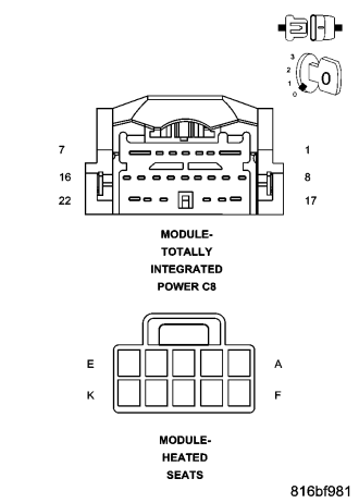
Turn the ignition off.
Disconnect the TIPM C8 harness connector.
Disconnect the Heated Seat Module harness connector.
Inspect the connector terminal for signs of corrosion build up and damage.
Visually inspect the wiring harness for any chafed, pierced, pinched or partially broken wires hidden in the wire insulation.
Were any of the above conditions found?
Yes
- Repair as necessary.
- Perform BODY VERIFICATION TEST VER 1. (Refer to 8 - ELECTRICAL/ELECTRONIC CONTROL MODULES - STANDARD PROCEDURE)
No
- Go To 3
3. INSPECT THE CABIN HEATER RELAY TERMINALS AND WIRE HARNESS FOR A CONDITION CAUSING HIGH CIRCUIT RESISTANCE
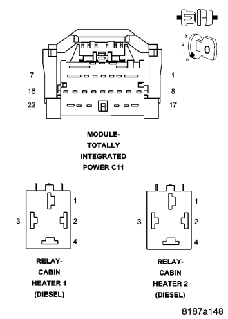
Disconnect the Cabin Heater Relays.
Disconnect the TIPM C11 harness connector.
Inspect the connector terminal for signs of corrosion build up and damage.
Visually inspect the wiring harness for any chafed, pierced, pinched or partially broken wires hidden in the wire insulation.
Were any of the above conditions found?
Yes
- Repair as necessary.
- Perform BODY VERIFICATION TEST VER 1. (Refer to 8 - ELECTRICAL/ELECTRONIC CONTROL MODULES - STANDARD PROCEDURE)
No
- Go To 4
4. CHECK THE (F937) FUSED IGNITION SWITCH OUTPUT (RUN) CIRCUIT FUNCTION
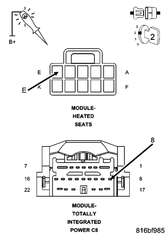
Connect one end of a jumper wire to the (F937) Fused Ignition Switch Output (RUN) circuit at the Heated Seat Module harness connector, and connect the other end to a clean chassis ground.
NOTE: The test light should be illuminated and bright. Compare the brightness to that of a direct connection to battery.
Using a 12 volt test light connected to 12 volts, probe the (F937) Fused Ignition Switch Output (RUN) circuit in the TIPM C8 harness connector.
Does the test light illuminate brightly?
Yes
- Go To 5
No
- Repair the (F937) Fused Ignition Switch Output (RUN) circuit for high resistance.
- Perform BODY VERIFICATION TEST VER 1. (Refer to 8 - ELECTRICAL/ELECTRONIC CONTROL MODULES - STANDARD PROCEDURE)
5. CHECK THE (F936) FUSED IGNITION SWITCH OUTPUT (RUN) CIRCUIT FUNCTION
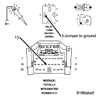
Connect one end of a jumper wire to the (F936) Fused Ignition Switch Output (RUN) circuit at the number 1 Cabin Heater Relay harness connector, and connect the other end to a clean chassis ground.
NOTE: The test light should be illuminated and bright. Compare the brightness to that of a direct connection to battery.
Using a 12 volt test light connected to 12 volts, probe the (F936) Fused Ignition Switch Output (RUN) circuit in the TIPM C11 harness connector.
Does the test light illuminate brightly?
Yes
- Go To 6
No
- Repair the (F936) Fused Ignition Switch Output (RUN) circuit for high resistance.
- Perform BODY VERIFICATION TEST VER 1. (Refer to 8 - ELECTRICAL/ELECTRONIC CONTROL MODULES - STANDARD PROCEDURE)
6. CHECK THE (F936) FUSED IGNITION SWITCH OUTPUT (RUN) CIRCUIT FUNCTION
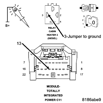
Connect one end of a jumper wire to the (F936) Fused Ignition Switch Output (RUN) circuit at the number 2 Cabin Heater Relay harness connector, and connect the other end to a clean chassis ground.
NOTE: The test light should be illuminated and bright. Compare the brightness to that of a direct connection to battery.
Using a 12 volt test light connected to 12 volts, probe the (F936) Fused Ignition Switch Output (RUN) circuit in the TIPM C11 harness connector.
Does the test light illuminate brightly?
Yes
- Go To 7
No
- Repair the (F936) Fused Ignition Switch Output (RUN) circuit for high resistance.
- Perform BODY VERIFICATION TEST VER 1. (Refer to 8 - ELECTRICAL/ELECTRONIC CONTROL MODULES - STANDARD PROCEDURE)
7. CHECK THE OUTPUT FROM THE TIPM ON THE (F937) FUSED IGNITION SWITCH OUTPUT (RUN) CIRCUIT
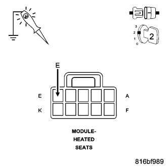
Reconnect the TIPM C8 harness connector.
Turn the ignition on.
Using a 12 volt test light connected to ground, probe the (F937) Fused Ignition Switch Output (RUN) circuit in the Heated Seat Module harness connector.
Does the test light illuminate brightly?
Yes
- Replace the Heated Seat Module in accordance with the service information.
- Perform BODY VERIFICATION TEST VER 1. (Refer to 8 - ELECTRICAL/ELECTRONIC CONTROL MODULES - STANDARD PROCEDURE)
No
- Go To 8
8. CHECK THE OUTPUT FROM THE TIPM ON THE (F936) FUSED IGNITION SWITCH OUTPUT (RUN) CIRCUIT
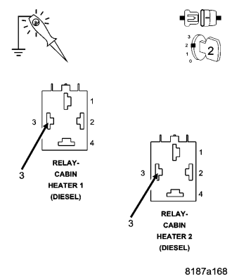
Reconnect the TIPM C11 harness connector.
Turn the ignition on.
Using a 12 volt test light connected to ground, probe the (F936) Fused Ignition Switch Output (RUN) circuit in the Cabin Heater Relay 1 and 2 harness connectors.
Does the test light illuminate brightly?
Yes
- Replace the appropriate Cabin Heater Relay in accordance with the service information.
- Perform BODY VERIFICATION TEST VER 1. (Refer to 8 - ELECTRICAL/ELECTRONIC CONTROL MODULES - STANDARD PROCEDURE)
No
- Replace the TIPM in accordance with the service information
- Perform BODY VERIFICATION TEST VER 1. (Refer to 8 - ELECTRICAL/ELECTRONIC CONTROL MODULES - STANDARD PROCEDURE)