HAZARD SWITCH
DESCRIPTION
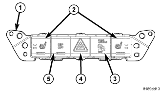
The hazard switch (4) is integral to the instrument panel switch pod (1), which is secured to the instrument panel center bezel just below the heater and air conditioner controls. A red, stencil-like International Control and Display Symbol icon for Hazard Warning identifies the hazard switch button. The remainder of the hazard switch circuitry is concealed within the instrument panel switch pod.
The hazard switch button has panel lamps dimmer controlled illumination for night visibility. The switch button unlatches to a slightly raised position when the hazard warning system is activated and the icon on the switch button will illuminate at an increased intensity while the turn signals and turn signal indicators are flashing. The switch button latches to a lowered position flush with the other push buttons in the switch pod when the hazard warning is deactivated.
All of the circuitry and components of the hazard switch are contained within a molded black plastic instrument panel switch pod housing. A single connector receptacle is integral to the back of the switch pod housing. The switch is connected to the vehicle electrical system through a dedicated take out and connector of the instrument panel wire harness.
The hazard switch cannot be adjusted or repaired and, if ineffective or damaged, the entire instrument panel switch pod unit must be replaced. (Refer to 8 - ELECTRICAL/INSTRUMENT CLUSTER/INSTRUMENT PANEL SWITCH POD - REMOVAL).
OPERATION
The status of the hazard switch is continually monitored by the circuitry within the instrument panel switch pod. The switch pod receives battery voltage at all times on a fused battery feed circuit, and a path to ground at all times through the instrument panel wire harness. The only other inputs to and outputs from the switch pod consist of electronic communication with the ElectroMechanical Instrument Cluster (EMIC) (also known as the Cab Compartment Node/CCN) over the single wire Local Interface Network (LIN) data bus.
Whenever the hazard switch is in its unlatched and raised position, the hazard warning system is selected and the switch pod circuitry sends an electronic hazard switch status message to the EMIC over the LIN data bus and the EMIC responds to this input by sending the appropriate electronic hazard system request messages to the Totally Integrated Power Module over the CAN data bus.
When the TIPM receives a hazard system request message it then controls hazard warning system operation and flash rate by controlling battery voltage outputs through high side drivers on the right and left turn signal feed circuits. The TIPM also sends the appropriate electronic messages back to the EMIC to control the illumination and flash rate of the right and left turn signal indicators, as well as to control the click rate of an electromechanical relay soldered onto the EMIC electronic circuit board that emulates the sound emitted by a conventional hazard warning flasher. The EMIC then sends messages back to the switch pod to control the illumination of the hazard switch push button.
The hard wired circuits for the instrument panel switch pod may be diagnosed using conventional diagnostic tools and procedures. Refer to the appropriate wiring information. However, conventional diagnostic methods will not prove conclusive in the diagnosis of the hazard warning switch or the electronic controls and communication between other modules and devices that provide some features of the hazard warning system. The most reliable, efficient, and accurate means to diagnose the hazard switch or the electronic controls and communication related to hazard warning system operation requires the use of a diagnostic scan tool. Refer to the appropriate diagnostic information.