SWITCH-STOP LAMP
DESCRIPTION
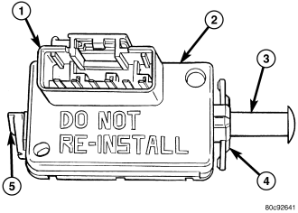
The brake lamp switch (2) is a three circuit, spring-loaded plunger actuated switch that is secured to the brake pedal support bracket on the dash panel under the instrument panel on the driver side of the vehicle. The molded plastic switch housing has an integral connector receptacle (1) containing six terminal pins and featuring a Connector Position Assurance (CPA) lock. The switch is connected to the vehicle electrical system through a dedicated take out of the unibody wire harness.
The switch plunger (3) extends through a mounting collar (4) on one end of the switch housing. The plunger has a one time telescoping self-adjustment feature that is activated after the switch is installed by moving an adjustment release lever (5) on the opposite end of the switch housing clockwise, until it locks into a position that is horizontal and parallel to the connector receptacle.
An installed brake lamp switch cannot be readjusted or repaired. If the switch is damaged, ineffective, or removed from its mounting position for any reason, it must be replaced with a new unit.
OPERATION
The brake lamp switch controls three independent circuits. These circuits are described as follows:
- Brake Lamp Switch Circuit - A normally open brake lamp switch circuit receives a battery voltage input, and supplies this battery voltage to the Center High Mounted Stop Lamp (CHMSL), the Totally Integrated Power Module (TIPM) and the ElectroMechanical Instrument Cluster (EMIC) (also known as the Cab Compartment Node/CCN) on a brake lamp switch output circuit only when the brake pedal is depressed (brake lamp switch plunger released). Then the TIPM regulates the appropriate battery voltage output to the brake lamps in the rear lamp units through a high side driver on the tail/stop lamp rear feed circuit.
- Brake Lamp Switch Signal Circuit - A normally closed brake lamp switch signal circuit receives a direct path to ground, and supplies this ground input to the Powertrain Control Module (PCM) on a brake lamp switch sense circuit only when the brake pedal is released (brake lamp switch plunger is depressed).
- Speed Control Circuit - A normally closed speed control circuit receives a battery voltage input from the Powertrain Control Module on a speed control supply circuit, and supplies this battery voltage to the speed control servo solenoids (dump, vacuum, and vent) on a speed control brake switch output circuit only when the speed control system is turned ON and the brake pedal is released (brake lamp switch plunger is depressed).
The components of the self-adjusting brake switch plunger consist of a two-piece telescoping plunger, a split plunger locking collar, and a release wedge. The release lever has a shaft with a wedge that spreads the plunger locking collar to an open or released position. After the switch is installed and the brake pedal is released, the plunger telescopes to the correct adjustment position. When the release lever is moved to the release position, the wedge is disengaged from the locking collar causing the collar to apply a clamping pressure to the two plunger halves, fixing the plunger length.
The brake lamp switch as well as the hard wired inputs and outputs of the switch may be diagnosed using conventional diagnostic tools and procedures. Refer to the appropriate wiring information.
REMOVAL
WARNING: To avoid serious or fatal injury, on vehicles equipped with airbags, disable the supplemental restraint system before attempting any steering wheel, steering column, airbag, occupant classification system, seat belt tensioner, impact sensor, or instrument panel component diagnosis or service. Disconnect and isolate the battery negative (ground) cable, then wait two minutes for the system capacitor to discharge before performing further diagnosis or service. This is the only sure way to disable the supplemental restraint system. Failure to take the proper precautions could result in accidental airbag deployment.
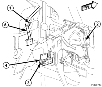
1. Disconnect and isolate the battery negative cable.
2. Locate the brake lamp switch (4) on the brake pedal support bracket (2) on the dash panel.
3. Disengage the wire harness retainer (1) from the brake pedal support bracket.
4. Disconnect the unibody wire harness take out and connector (5) from the brake lamp switch.
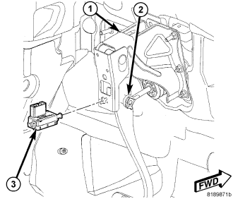
5. Rotate the brake lamp switch housing (3) clockwise about 30 degrees to align the tabs on the switch locking collar with the keyed hole in the brake pedal support bracket (1).
6. Pull the switch straight back from the keyed hole to remove it from the bracket.
CAUTION: The brake lamp switch self-adjusting switch plunger is a one time only feature. If the switch is removed from the mounting bracket, it MUST be replaced with a new switch.
7. Discard the removed brake lamp switch .
INSTALLATION
WARNING: To avoid serious or fatal injury, on vehicles equipped with airbags, disable the supplemental restraint system before attempting any steering wheel, steering column, airbag, occupant classification system, seat belt tensioner, impact sensor, or instrument panel component diagnosis or service. Disconnect and isolate the battery negative (ground) cable, then wait two minutes for the system capacitor to discharge before performing further diagnosis or service. This is the only sure way to disable the supplemental restraint system. Failure to take the proper precautions could result in accidental airbag deployment.
CAUTION: The brake lamp switch self-adjusting switch plunger is a one time only feature. If the switch is removed from the mounting bracket, it MUST be replaced with a new switch.
1. Depress and hold the brake pedal (2) in the depressed position.
2. Align the tabs on the brake lamp switch (3) locking collar with the keyed hole in the brake pedal mounting bracket (1) on the dash panel.
3. Insert the tabs on the brake lamp switch locking collar through the keyed hole in the brake pedal mounting bracket until the switch housing is firmly seated against the bracket.
4. Rotate the switch housing counterclockwise about 30 degrees to engage the tabs on the locking collar with the pedal mounting bracket.
CAUTION: Do not release or pull up on the brake pedal before the switch plunger adjustment has been completed.
5. Release the brake pedal, but do not pull it upward.
6. Reconnect the unibody wire harness connector (5) to the brake lamp switch (4).
7. Engage the wire harness retainer (1) in the locator hole in the brake pedal support bracket (2).
8. Rotate the plunger adjustment release lever (3) clockwise until it locks into place. The lever should be parallel to the brake lamp switch connector receptacle. This action will set the switch plunger length to a final adjustment position and cannot be undone. If not performed properly the first time, a new brake lamp switch must be installed.
9. Reconnect the battery negative cable.