LINE-A/C LIQUID
DESCRIPTION
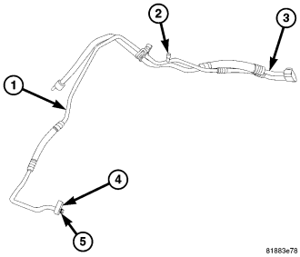
The A/C liquid line (1) is the refrigerant line that carries refrigerant from the A/C condenser to the A/C evaporator. The A/C liquid line contains the low side service port (2) and the variable A/C orifice tube. The A/C liquid line is only serviced as an assembly with the upper A/C suction line (3).
NOTE: Replacement of the refrigerant line O-ring seals and gaskets is required anytime a refrigerant line is opened. Failure to replace the rubber O-ring seals and metal gaskets could result in a refrigerant system leak.
The A/C liquid/suction line assembly has no serviceable parts except for the metal gaskets (4), rubber O-ring seals (5) and the low side service port valve core. The O-ring seals used on the connections are made from a special type of rubber not affected by R-134a refrigerant. The O-ring seals and gaskets must be replaced whenever the A/C liquid/suction line assembly is removed.
The A/C liquid/suction line assembly cannot be repaired and must be replaced if found to be leaking or damaged, or if an internal failure of the A/C compressor has occurred.
REMOVAL
WARNING: Review safety precautions and warnings in this group before performing this procedure (refer to 24 - HEATING & AIR CONDITIONING/PLUMBING - WARNING) and (refer to 24 - HEATING & AIR CONDITIONING/PLUMBING - CAUTION). Failure to follow the warnings and cautions could result in possible personal injury or death.
NOTE: The A/C liquid line is only serviced as an assembly with the upper A/C suction line.
NOTE: LHD model shown in illustrations. RHD model similar.
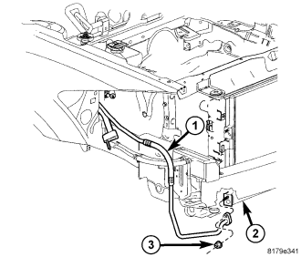
NOTE: Illustration shown with front fascia removed for clarity.
1. Disconnect and isolate the negative battery cable.
2. Recover the refrigerant from the refrigerant system (refer to 24 - HEATING & AIR CONDITIONING/PLUMBING - STANDARD PROCEDURE - REFRIGERANT SYSTEM RECOVERY).
3. Raise and support the vehicle.
4. Remove the A/C accumulator (refer to 24 - HEATING & AIR CONDITIONING/PLUMBING/ACCUMULATOR-A/C - REMOVAL).
5. Reach up through the opening in the bottom of the front fascia located in the right front corner of the vehicle and remove the nut (3) that secures the A/C liquid line (1) to the A/C condenser (2).
6. Disconnect the A/C liquid line from the A/C condenser and remove and discard the O-ring seal and gasket.
7. Install plugs in, or tape over the opened refrigerant line fittings and the condenser and accumulator ports.
8. Lower the vehicle.
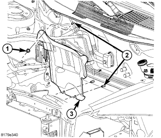
9. Remove the three nuts (1) that secure the heat shield (3) to the studs (2) located on the dash panel in the engine compartment and remove the heat shield.
NOTE: It is only necessary to position the engine coolant reservoir and the power steering fluid reservoir out of the way. Draining of the coolant and brake fluid is not required when servicing the washer bottle.
10. Remove the windshield washer reservoir (refer to 8 - ELECTRICAL/WIPERS/WASHERS/WASHER RESERVOIR - REMOVAL).
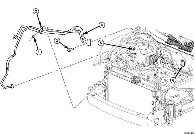
11. Remove the nut (1) that secures the refrigerant line retaining bracket (2) to the right front strut tower (5).
12. On RHD models, disengage the retainers that secure the power brake booster vacuum supply hose to the dash panel and position the vacuum line out of the way.
13. Remove the bolt (3) that secures the A/C liquid and suction line assembly (4) to the A/C evaporator (6).
14. Disconnect the A/C liquid and suction line assembly from the A/C evaporator and remove and discard the dual-plane seals.
15. Install plugs in, or tape over the opened refrigerant line fittings and the evaporator ports.
16. Remove the A/C liquid and suction line assembly from the engine compartment.
INSTALLATION
CAUTION: Be certain to adjust the refrigerant oil level when servicing the A/C refrigerant system (refer to 24 - HEATING & AIR CONDITIONING/PLUMBING/REFRIGERANT OIL - STANDARD PROCEDURE - REFRIGERANT OIL LEVEL). Failure to properly adjust the refrigerant oil level will prevent the A/C system from operating as designed and can cause serious A/C compressor damage.
CAUTION: The A/C liquid line must be replaced if an internal failure of the A/C compressor has occurred. Failure to replace the A/C liquid line can prevent the A/C system from operating as designed and can cause serious A/C compressor damage.
NOTE: When replacing multiple A/C system components, refer to the Refrigerant Oil Capacities chart to determine how much oil should be added to the refrigerant system (refer to 24 - HEATING & AIR CONDITIONING/PLUMBING/REFRIGERANT OIL - STANDARD PROCEDURE - REFRIGERANT OIL LEVEL).
NOTE: Replacement of the refrigerant line O-ring seals and gaskets is required anytime a refrigerant line is opened. Failure to replace the rubber O-ring seals and metal gaskets could result in a refrigerant system leak.
NOTE: LHD model shown in illustrations. RHD model similar.
1. Position the A/C liquid and suction line assembly (4) into the engine compartment.
2. Remove the tape or plugs from the refrigerant line fittings and the evaporator ports.
3. Lubricate the rubber O-rings on new dual-plane seals with clean refrigerant oil and install the seals onto the liquid and suction line fittings. Use only the specified seals as they are made of special materials compatible to the R-134a system. Use only refrigerant oil of the type recommended for the A/C compressor in the vehicle.
4. Connect the A/C liquid and suction line assembly to the A/C evaporator (6).
5. Install the bolt (3) that secures the A/C liquid and suction line assembly to the A/C evaporator. Tighten the bolt to 12 N·m (105 in. lbs.).
6. On RHD models, engage the retainers that secure the power brake booster vacuum supply hose to the dash panel.
7. Install the nut (1) that secures the refrigerant line bracket (2) to the right front strut tower (5). Tighten the nut to 4.5 N·m (40 in. lbs.).
8. Install the windshield washer reservoir, power steering reservoir and the engine coolant reservoir (refer to 8 - ELECTRICAL/WIPERS/WASHERS/WASHER RESERVOIR - INSTALLATION).
9. Position the heat shield (3) onto the studs (2) located on the dash panel in the engine compartment.
10. Install the three nuts (1) that secure the heat shield to the dash panel. Tighten the nuts to 1 N·m (10 in. lbs.).
NOTE: Illustration shown with front fascia removed for clarity.
11. Raise and support the vehicle.
12. Remove the tape or plugs from the liquid line fitting and the condenser port.
13. Lubricate a new rubber O-ring seal with clean refrigerant oil and install it and a new gasket onto the liquid line fitting. Use only the specified O-ring as it is made of a special material for the R-134a system. Use only refrigerant oil of the type recommended for the A/C compressor in the vehicle.
14. Reach up through the opening in the bottom of the front fascia and connect the A/C liquid line (1) to the A/C condenser (2) and install the retaining nut (3). Tighten the nut to 5 N·m (44 in. lbs.).
15. Install the A/C accumulator (refer to 24 - HEATING & AIR CONDITIONING/PLUMBING/ACCUMULATOR - INSTALLATION).
16. Lower the vehicle.
17. Reconnect the negative battery cable.
CAUTION: Do NOT run the engine with a vacuum pump in operation or with a vacuum present within the A/C system. Failure to follow this caution will result in serious A/C compressor damage.
18. Evacuate the refrigerant system (refer to 24 - HEATING & AIR CONDITIONING/PLUMBING - STANDARD PROCEDURE - REFRIGERANT SYSTEM EVACUATE)
19. Adjust the refrigerant oil level (refer to 24 - HEATING & AIR CONDITIONING/PLUMBING/REFRIGERANT OIL - STANDARD PROCEDURE - REFRIGERANT OIL LEVEL).
20. Charge the A/C system (refer to 24 - HEATING & AIR CONDITIONING/PLUMBING - STANDARD PROCEDURE - REFRIGERANT SYSTEM CHARGE).