DIAGNOSIS AND TESTING
B18BB-WINDOW CONTROL CIRCUIT LOW - TIPM
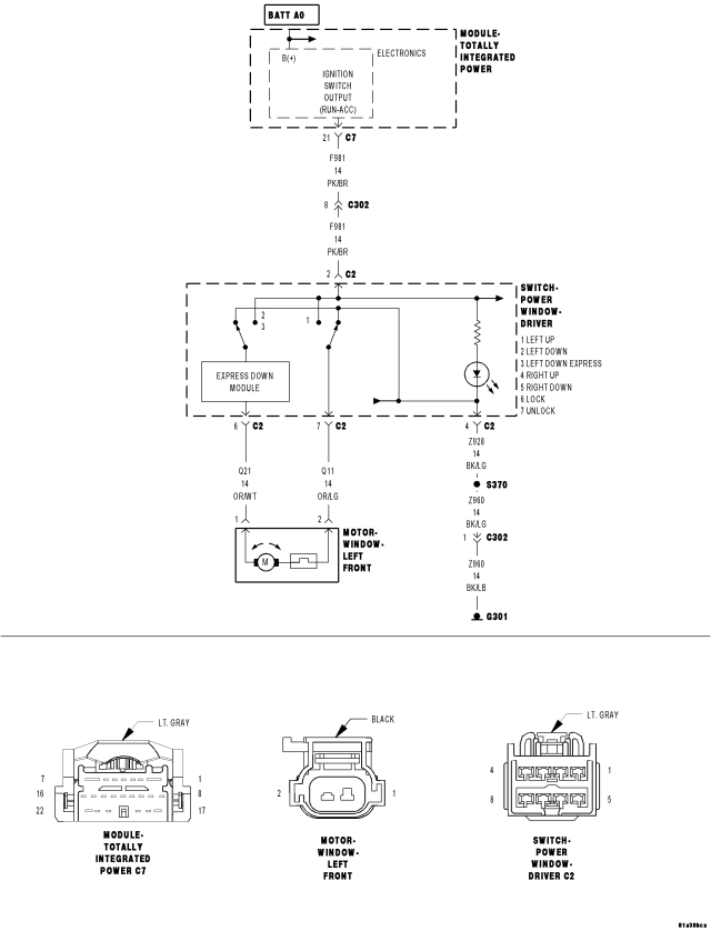
For a complete wiring diagram Refer to Section 8W.
- When Monitored:
Whenever the module is awake.
- Set Condition:
When the Totally Integrated Power Module (TIPM) senses a draw of between 65 and 100 amps for 80 ms., this code will set.
NOTE: The most probable cause for this DTC to set is that the driver held all four window switches down for an extended period of time thereby causing the high side driver, in the TIPM, to overheat and cut out. Once the high side driver is opened, it will remain open until the next key cycle. However, the code will remain as stored.
| Possible Causes |
| (F981) IGNITION SWITCH OUTPUT CIRCUIT SHORT TO GROUND |
| ALL FOUR WINDOW SWITCHES HELD DOWN FOR AN EXTENDED PERIOD OF TIME |
| DRIVER POWER WINDOW SWITCH |
| TOTALLY INTEGRATED POWER MODULE (TIPM) |
Diagnostic Test
1. TEST FOR INTERMITTENT CONDITIONTurn the ignition on.
With the scan tool, record and erase DTC's
Cycle the ignition switch off then on.
Operate the Driver Window Switch in all positions several times.
Wait 30 seconds.
With the scan tool, read DTC's.
Does the scan tool display B18BB–WINDOW CONTROL CIRCUIT LOW?
Yes
- Go To 3
No
- Go To 2
2. TEST WINDOW MOTORS
Do all window motors operate properly at this time?
No
- Go To 5
Yes
- The conditions that caused this code to set are not present at this time. Check for a sticking switch and using the wiring diagram/schematic as a guide, inspect the wiring and connectors.
- Perform BODY VERIFICATION TEST - VER 1. (Refer to 8 - ELECTRICAL/ELECTRONIC CONTROL MODULES - STANDARD PROCEDURE)
3. (F981) IGNITION SWITCH OUTPUT CIRCUIT SHORT TO GROUND
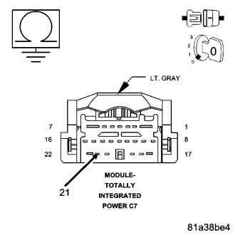
Turn the ignition off.
Disconnect the TIPM C7 connector.
Measure the resistance between ground and the (F981) Ignition Switch Output circuit in the TIPM C7 connector.
Is the resistance below 10,000.0 ohms?
No
- Replace the Totally Integrated Power Module in accordance with service information.
- Perform BODY VERIFICATION TEST - VER 1. (Refer to 8 - ELECTRICAL/ELECTRONIC CONTROL MODULES - STANDARD PROCEDURE)
Yes
- Go To 4
4. DRIVER POWER WINDOW SWITCH
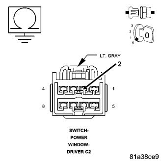
Turn the ignition off.
Disconnect the Driver Power Window Switch connector.
Measure the resistance between ground and the (F981) Ignition Switch Output circuit.
Is the resistance below 10,000.0 ohms?
Yes
- Repair the (F981) Ignition Switch Output circuit for a short to ground.
- Perform BODY VERIFICATION TEST - VER 1. (Refer to 8 - ELECTRICAL/ELECTRONIC CONTROL MODULES - STANDARD PROCEDURE)
No
- Replace the Driver Power Window Switch
- Perform BODY VERIFICATION TEST - VER 1. (Refer to 8 - ELECTRICAL/ELECTRONIC CONTROL MODULES - STANDARD PROCEDURE)
5. WINDOW MOTOR
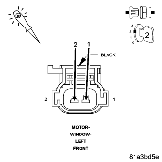
Turn the ignition off.
Disconnect the inoperative window motor connector.
Connect a 12 volt test light between the Window Driver (UP) circuit and the Window Driver (DOWN) circuit.
NOTE: The graphic shows the Left Front Window Motor (LHD), all others are similar,
Turn the ignition on.
Operate the Driver Window Switch in both directions while observing the test light.
Does the test light illuminate brightly when the switch in held in both directions?
No
- Go To 6
Yes
- Replace the Window Motor in accordance with service information.
- Perform BODY VERIFICATION TEST - VER 1. (Refer to 8 - ELECTRICAL/ELECTRONIC CONTROL MODULES - STANDARD PROCEDURE)
6. WINDOW DRIVER (UP) CIRCUIT SHORT TO GROUND
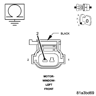
Turn the ignition off.
Disconnect the Driver Power Window Switch connector.
Measure the resistance between ground and the Window Driver (Up) circuit in the motor connector.
Is the resistance below 10.0 ohms?
Yes
- Repair the Window Driver (Up) circuit for a short to ground. If this is not the driver window, the short could be from the master switch to the motor. Using the Power Window Schematic check for the proper circuit.
- Perform BODY VERIFICATION TEST - VER 1. (Refer to 8 - ELECTRICAL/ELECTRONIC CONTROL MODULES - STANDARD PROCEDURE)
No
- Go To 7
7. WINDOW DRIVER (DOWN) CIRCUIT SHORT TO GROUND
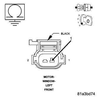
Measure the resistance between ground and the Window Driver (Down) circuit in the motor connector.
Is the resistance below 10.0 ohms?
Yes
- Repair the Window Driver (Down) circuit for a short to ground. If this is not the driver window, the short could be from the master switch to the motor. Check the Power Window Schematic for the proper circuit.
- Perform BODY VERIFICATION TEST - VER 1. (Refer to 8 - ELECTRICAL/ELECTRONIC CONTROL MODULES - STANDARD PROCEDURE)
No
- Test Complete.
- Perform BODY VERIFICATION TEST - VER 1. (Refer to 8 - ELECTRICAL/ELECTRONIC CONTROL MODULES - STANDARD PROCEDURE)
B191D-WINDOW CONTROL CIRCUIT OVERCURRENT - TIPM
For a complete wiring diagram Refer to Section 8W.
- When Monitored:
Whenever the module is awake.
- Set Condition:
When the Totally Integrated Power Module (TIPM) senses a draw of over 35 amps for over 120 ms. on the F981 Ignition Switch Output circuit, this code will set
NOTE: A possible cause for this DTC to set would be if the driver held more than one window switch down for an extended period of time thereby causing the high side driver, in the TIPM, to overheat and cut out. Once the high side driver is opened, it will remain open until the next key cycle. However, the code will remain as stored.
| Possible Causes |
| MORE THAN ONE WINDOW SWITCH HELD DOWN TOO LONG |
| WINDOW DRIVER (DOWN) CIRCUIT SHORT TO GROUND |
| WINDOW DRIVER (UP) CIRCUIT SHORT TO GROUND |
| WINDOW MOTOR |
| TOTALLY INTEGRATED POWER MODULE (TIPM) |
Diagnostic Test
1. TEST FOR INTERMITTENT CONDITIONTurn the ignition on.
With the scan tool, record and erase DTC's
Cycle the ignition switch off then on.
Operate the Driver Window Switch in all positions several times.
Wait 30 seconds.
With the scan tool, read DTC's.
Does the scan tool display B191D–WINDOW CONTROL CIRCUIT OVERCURRENT?
Yes
- Go To 3
No
- Go To 2
STORED CODE
2. TEST WINDOW MOTORSDo all window motors operate properly at this time?
No
- Disconnect the inoperative motor connector. Using the Power Window schematic, test both Driver circuits, at the motor connector, for a short to ground or to each other. If the circuits are operational, replace the window motor (regulator) in accordance with service information.
- Perform BODY VERIFICATION TEST - VER 1. (Refer to 8 - ELECTRICAL/ELECTRONIC CONTROL MODULES - STANDARD PROCEDURE)
Yes
- The conditions that caused this code to set are not present at this time. Check for a sticking switch and using the wiring diagram/schematic as a guide, inspect the wiring and connectors.
- Perform BODY VERIFICATION TEST - VER 1. (Refer to 8 - ELECTRICAL/ELECTRONIC CONTROL MODULES - STANDARD PROCEDURE)
3. WINDOW MOTOR
Turn the ignition off.
Disconnect the inoperative window motor connector.
Turn the ignition on.
Connect a 12 volt test light between the Window Driver (UP) circuit and the Window Driver (DOWN) circuit.
NOTE: The graphic shows the Left Front Window Motor (LHD), all others are similar,
Turn the ignition on.
Operate the Driver Window Switch in both directions while observing the test light.
Does the test light illuminate brightly when the switch in held in both directions?
No
- Go To 4
Yes
- Replace the Window Motor in accordance with service information.
- Perform BODY VERIFICATION TEST - VER 1. (Refer to 8 - ELECTRICAL/ELECTRONIC CONTROL MODULES - STANDARD PROCEDURE)
4. WINDOW DRIVER (UP) CIRCUIT SHORT TO GROUND
Turn the ignition off.
Disconnect the Driver Power Window Switch connector.
Measure the resistance between ground and the Window Driver (Up) circuit in the motor connector.
Is the resistance below 1000.0 ohms?
Yes
- Repair the Window Driver (Up) circuit for a short to ground. If this is not the driver window, the short could be from the master switch to the motor. Using the Power Window Schematic, check for the proper circuit.
- Perform BODY VERIFICATION TEST - VER 1. (Refer to 8 - ELECTRICAL/ELECTRONIC CONTROL MODULES - STANDARD PROCEDURE)
No
- Go To 5
5. WINDOW DRIVER (DOWN) CIRCUIT SHORT TO GROUND
Measure the resistance between ground and the Window Driver (Down) circuit in the motor connector.
Is the resistance below 1000.0 ohms?
Yes
- Repair the Window Driver (Down) circuit for a short to ground. If this is not the driver window, the short could be from the master switch to the motor. Check the Power Window Schematic for the proper circuit.
- Perform BODY VERIFICATION TEST - VER 1. (Refer to 8 - ELECTRICAL/ELECTRONIC CONTROL MODULES - STANDARD PROCEDURE)
No
- Test Complete.
- Perform BODY VERIFICATION TEST - VER 1. (Refer to 8 - ELECTRICAL/ELECTRONIC CONTROL MODULES - STANDARD PROCEDURE)