ARM-LOWER CONTROL
REMOVAL
1. Raise and support the vehicle. (Refer to LUBRICATION & MAINTENANCE/HOISTING - STANDARD PROCEDURE)
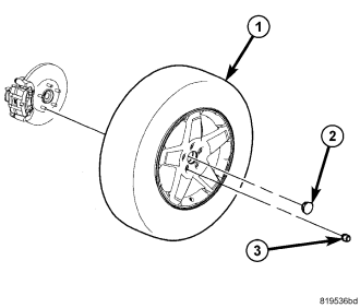
2. Remove the wheel mounting nuts (3), then the tire and wheel assembly (1).
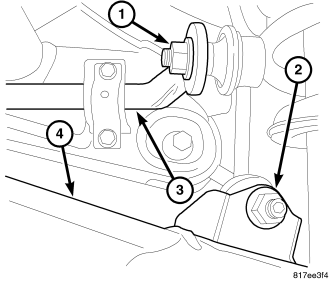
3. If equipped, while holding the stabilizer bar link lower stud stationary, remove the nut (2) securing the link to the lower control arm (4).
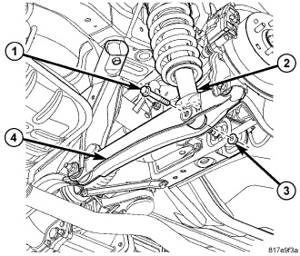
4. Remove the lower shock mounting nut (3) and bolt (1).
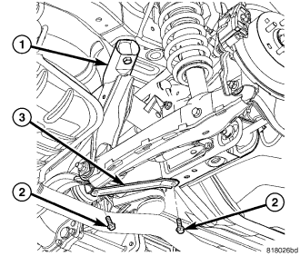
5. Remove the stay brace (3) mounting screws (2). Remove the stay brace.
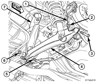
6. Remove the nut (2) and bolt (3) securing the lower control arm (4) to the trailing link (1).
7. Remove the nut (6) and bolt (5) securing the lower control arm (4) to the crossmember (7).
8. Remove the lower control arm (4).
INSTALLATION
1. Position the lower control arm and install the bolt (5) and nut (6) securing the lower control arm (4) to the crossmember (7). Do not tighten at this time.
2. Install the bolt (3) and nut (2) securing the lower control arm (4) to the trailing link (1). Do not tighten at this time.
3. Install the stay brace (3) on the crossmember (1). Install and tighten the mounting screws (2) to 25 N·m (18 ft. lbs.).
4. Install the mounting bolt (1) and nut (3) fastening the shock assembly (2) to the lower control arm (4). Do not tighten at this time.
NOTE: When attaching a stabilizer bar link to the lower control arm it is important that the lower mounting stud be positioned properly. The lower mounting stud on the right side link needs to point toward the rear of the vehicle when inserted through the lower control arm mounting flange. The left side link lower stud needs to point toward the front of the vehicle. Otherwise the suspension geometry will not function properly.
5. If equipped, attach the stabilizer bar link to the lower control arm (4). Install the nut (2) and while holding the stabilizer bar link lower stud stationary, tighten the nut (2) to 58 N·m (43 ft. lbs.).
6. Install the tire and wheel assembly (1) (Refer to 22 - TIRES/WHEELS - INSTALLATION). Install and tighten the wheel mounting nuts (3) to 135 N·m (100 ft. lbs.).
7. Lower the vehicle.
8. Position the vehicle on an alignment rack/drive-on lift. Raise the vehicle as necessary to access mounting bolts and nuts.
9. Tighten the lower control arm mounting bolt nut at the crossmember to 95 N·m (70 ft. lbs.).
10. Tighten the lower control arm mounting bolt nut at the trailing link to 95 N·m (70 ft. lbs.).
11. Tighten the shock assembly lower mounting bolt nut to 99 N·m (73 ft. lbs.).
12. Perform wheel alignment as necessary. (Refer to 2 - SUSPENSION/WHEEL ALIGNMENT - STANDARD PROCEDURE)