RESTRAINTS
DESCRIPTION
An occupant restraint system is standard factory-installed safety equipment on this vehicle. Available occupant restraints for this vehicle include both active and passive types. Active restraints are those which require the vehicle occupants to take some action to employ, such as fastening a seat belt; while passive restraints require no action by the vehicle occupants to be employed.
ACTIVE RESTRAINTS
The active restraints for this vehicle include:
- Child Restraint Anchors - All vehicles are equipped with three, fixed-position, child seat upper tether anchors for the second row seating. A single upper tether anchor is integral to the back of the left seat back panel, and two more are integral to the right seat back panel. Two lower anchors are also provided for each outboard seating position. Three lower anchors are integral to the seat back hinge brackets, while the fourth is integral to a dedicated child anchor bracket. All lower anchors are accessed from the front of the second row seat where the seat back meets the seat cushion.
- Front Seat Belts - Both front seating positions are equipped with three-point seat belt systems employing a lower B-pillar mounted inertia latch-type emergency locking retractors, height-adjustable upper B-pillar mounted turning loops, a traveling lower seat belt anchor secured to the outboard side of the seat frame, and a traveling end-release seat belt buckle secured to the inboard side of the seat frame. The driver side front seat belt buckle includes an integral seat belt switch that detects whether the driver side front seat belt has been fastened.
- Second Row Seat Belts - All three second row seating positions are equipped with three-point seat belt systems. The outboard seating position belts employ lower C-pillar mounted inertia latch-type emergency locking retractors, fixed position upper C-pillar mounted turning loops and fixed lower seat belt anchors secured to the rear floor panel. The second row seat center seating position has an inertia latch-type emergency locking retractor that is secured within the right D-pillar and has a dedicated, keyed anchor buckle that allows the belt anchor to be quickly detached when the right second row seat back is folded down for additional cargo space. All of the second row seat belt retractors for this vehicle are also switchable from an emergency locking retractor to an automatic locking retractor for compatibility with child seats. The center seating position belt lower anchor buckle is secured along with the right outboard seat belt buckle to the rear floor panel through the child lower anchor bracket. All three second row seat belts have fixed end-release seat belt buckles.
PASSIVE RESTRAINTS
The passive restraints available for this vehicle include the following:
- Dual Front Airbags - Multistage driver and front passenger airbags are used in this vehicle. This airbag system is a passive, inflatable, Supplemental Restraint System (SRS) and vehicles with this equipment can be readily identified by the SRS - AIRBAG logo molded into the driver airbag trim cover in the center of the steering wheel and also into the passenger airbag door on the instrument panel above the glove box. Vehicles with the airbag system can also be identified by the airbag indicator, which will illuminate in the ElectroMechanical Instrument Cluster (EMIC) (also known as the Cab Compartment Node/CCN) for about seven seconds as a bulb test each time the ignition switch is turned to the ON position. A pyrotechnic-type seat belt tensioner is also integral to the front seat belt retractors mounted on the lower inner B-pillars to work in conjunction with the dual front airbags.
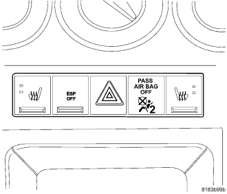
- Occupant Classification System - Vehicles manufactured for sale in North America (except Mexico) also include an Occupant Classification System (OCS) with components that are located on the front seats. These components include an Occupant Classification Module (OCM) and four seat weight sensors on the passenger seat, and seat track position sensors on both the driver and passenger front seats. Vehicles equipped with the OCS components can be readily identified by a passenger airbag on/off indicator located to the right of the hazard switch button in the instrument panel switch pod near the base of the instrument panel center bezel.
- Side Curtain Airbags - Side curtain airbags are standard equipment in this vehicle when it is also equipped with dual front airbags. This airbag system is a passive, inflatable, Supplemental Restraint System (SRS) and vehicles with this equipment can be readily identified by a molded identification trim button with the SRS - AIRBAG logo located on the top of each B-pillar upper trim panel near the headliner.
- Seat Airbags - Seat mounted airbags are optional equipment in this vehicle. This airbag system is a passive, inflatable, Supplemental Restraint System (SRS) and vehicles with this equipment can be readily identified by a sewn tag with the SRS - AIRBAG logo located on the outboard side of the front seat back trim cover.
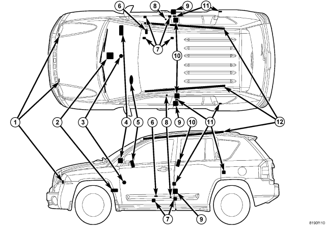
The supplemental restraint system includes the following major components, which are described in further detail elsewhere in this service information:
- Airbag Indicator - The airbag indicator is integral to the ElectroMechanical Instrument Cluster (EMIC) (also known as the Cab Compartment Node/CCN), which is located on the instrument panel in front of the driver.
- Clockspring - The clockspring is located near the top of the steering column, directly beneath the steering wheel.
- Driver Airbag (5) - The driver airbag is located in the center of the steering wheel, beneath the driver airbag trim cover.
- Driver Knee Blocker - The driver knee blocker is a structural unit secured to the back side of and integral to the instrument panel steering column opening cover.
- Front Impact Sensor (1) - Two front impact sensors are used on vehicles equipped with dual front airbags, one left side and one right side. One sensor is located on the back side of each vertical member of the radiator support.
- Occupant Classification Module (6) - Vehicles equipped with the Occupant Classification System (OCS) include an Occupant Classification Module (OCM) which is secured to the forward end of the seat cushion pan under the passenger side front seat cushion.
- Occupant Restraint Controller (2) - The Occupant Restraint Controller (ORC) is located on a mount on the floor panel transmission tunnel forward of the transmission gear selector, and is concealed behind the instrument panel center support.
- Passenger Airbag (4) - The passenger airbag is located in the instrument panel, beneath the passenger airbag door on the instrument panel top cover and above the glove box on the passenger side of the vehicle.
- Passenger Airbag On/Off Indicator (3) - Vehicles with the Occupant Classification System (OCS) include a passenger airbag on/off indicator which is located in the instrument panel switch pod near the base of the instrument panel lower center bezel.
- Passenger Knee Blocker - The passenger knee blocker is a structural reinforcement that is integral to and concealed within the glove box door.
- Seat Airbag (10) - An optional seat airbag unit is secured to each outboard front seat back frame, where it is concealed beneath the seat back trim cover and foam.
- Seat Belt Tensioner (9) - A seat belt tensioner is integral to both front seat belt retractor units on vehicles equipped with dual front airbags. The seat belt retractor tensioner units are secured to each lower inner B-pillar and are concealed behind the lower B-pillar trim.
- Seat Track Position Sensor (8) - The Occupant Classification System (OCS) includes two seat track position sensors. One sensor is located on the inboard side of one of the seat adjuster tracks on both the driver and the passenger front seats.
- Seat Weight Sensor (7) - Vehicles equipped with the Occupant Classification System (OCS) include four seat weight sensors, one on each corner of the passenger side front seat between the seat cushion frame and the seat track.
- Side Curtain Airbag (12) - A side curtain airbag is secured to each inside roof side rail above the headliner, and extends from the A-pillar to just behind the C-pillar.
- Side Impact Sensor (11) - Four side impact sensors are used, two on each side of the vehicle. One sensor is located behind the B-pillar trim near the belt line of each B-pillar and one sensor is located behind the quarter panel trim near the belt line of each C-pillar.
The ORC, the OCM, and the EMIC each contain a microprocessor and programming that allow them to communicate with each other using the Controller Area Network (CAN) data bus. This method of communication is used by the ORC for control of the airbag indicator in the EMIC. (Refer to 8 - ELECTRICAL/ELECTRONIC CONTROL MODULES/COMMUNICATION - DESCRIPTION).
Hard wired circuitry connects the supplemental restraint system components to each other through the electrical system of the vehicle. These hard wired circuits are integral to several wire harnesses, which are routed throughout the vehicle and retained by many different methods. These circuits may be connected to each other, to the vehicle electrical system, and to the supplemental restraint system components through the use of a combination of soldered splices, splice block connectors, and many different types of wire harness terminal connectors and insulators. Refer to the appropriate wiring information. The wiring information includes wiring diagrams, proper wire and connector repair procedures, further details on wire harness routing and retention, as well as pin-out and location views for the various wire harness connectors, splices and grounds.
OPERATION
ACTIVE RESTRAINTS
The primary passenger restraints in this or any other vehicle are the standard equipment factory-installed seat belts and child restraint anchors. Seat belts and child restraint anchors are referred to as an active restraint because the vehicle occupants are required to physically fasten and properly adjust these restraints in order to benefit from them.
PASSIVE RESTRAINTS
The passive restraints are referred to as a supplemental restraint system because they were designed and are intended to enhance the protection for the occupants of the vehicle only when used in conjunction with the seat belts. They are referred to as passive restraints because the vehicle occupants are not required to do anything to make them operate; however, the vehicle occupants must be wearing their seat belts in order to obtain the maximum safety benefit from the factory-installed supplemental restraint system.
The supplemental restraint system electrical circuits are continuously monitored and controlled by a microprocessor and software contained within the Occupant Restraint Controller (ORC). An airbag indicator in the ElectroMechanical Instrument Cluster (EMIC) (also known as the Cab Compartment Node/CCN) illuminates for about seven seconds as a bulb test each time the ignition switch is turned to the ON or START positions. Following the bulb test, the airbag indicator is turned ON or OFF by the ORC to indicate the status of the supplemental restraint system. If the airbag indicator comes ON at any time other than during the bulb test, it indicates that there is a problem in the supplemental restraint system electrical circuits. Such a problem may cause airbags not to deploy when required, or to deploy when not required.
Deployment of the supplemental restraints depends upon the angle and severity of an impact. Deployment is not based upon vehicle speed; rather, deployment is based upon the rate of deceleration as measured by the forces of gravity (G force) upon the impact sensors. When an impact is severe enough, the microprocessor in the ORC signals the inflator of the appropriate airbag units to deploy their airbag cushions. The front seat belt tensioners are provided with a deployment signal by the ORC in conjunction with the front airbags. The optional seat airbags are provided with a deployment signal by the ORC in conjunction with the side curtain airbag for the same side of the vehicle.
During a frontal vehicle impact, the knee blockers work in concert with properly fastened and adjusted seat belts to restrain both the driver and the front seat passenger in the proper position for an airbag deployment. The knee blockers also absorb and distribute the crash energy from the driver and the front seat passenger to the structure of the instrument panel. The seat belt tensioners remove the slack from the front seat belts to provide further assurance that the driver and front seat passenger are properly positioned and restrained for an airbag deployment.
Typically, the vehicle occupants recall more about the events preceding and following a collision than they do of an airbag deployment itself. This is because the airbag deployment and deflation occur very rapidly. In a typical 48 kilometer-per-hour (30 mile-per-hour) barrier impact, from the moment of impact until the airbags are fully inflated takes about 40 milliseconds. Within one to two seconds from the moment of impact, the airbags are almost entirely deflated. The times cited for these events are approximations, which apply only to a barrier impact at the given speed. Actual times will vary somewhat, depending upon the vehicle speed, impact angle, severity of the impact, and the type of collision.
When the ORC monitors a problem in any of the supplemental restraint system circuits or components, including the seat belt tensioners, it stores a fault code or Diagnostic Trouble Code (DTC) in its memory circuit and sends an electronic message to the EMIC to turn ON the airbag indicator. The hard wired circuits between components related to the supplemental restraint system may be diagnosed using conventional diagnostic tools and procedures. Refer to the appropriate wiring information. The wiring information includes wiring diagrams, proper wire and connector repair procedures, details of wire harness routing and retention, connector pin-out information and location views for the various wire harness connectors, splices and grounds.
However, conventional diagnostic methods will not prove conclusive in the diagnosis of the supplemental restraint system or the electronic controls or communication between other modules and devices that provide features of the supplemental restraint system. The most reliable, efficient, and accurate means to diagnose the supplemental restraint system or the electronic controls and communication related to supplemental restraint system operation, as well as the retrieval or erasure of a DTC requires the use of a diagnostic scan tool. Refer to the appropriate diagnostic information.
OCCUPANT CLASSIFICATION SYSTEM
In vehicles equipped with the Occupant Classification System (OCS), the OCS automatically suppresses or enables passenger airbag and seat belt tensioner operation based upon whether or not the passenger side front seat is occupied and, if the seat is occupied, classifies the size of the occupant or whether the seat is occupied by a child seat. The passenger airbag and seat belt tensioner are disabled when the system senses the seat is occupied by a child seat or a person below a minimum weight threshold.
The OCS has an Occupant Classification Module (OCM) that monitors inputs from the seat weight sensors under the passenger side front seat cushion and from the seat track position sensors on the passenger side and driver side seat adjuster tracks. Based upon those inputs the microprocessor within the OCM classifies the occupant of the passenger side front seat, and the proximity of each front seat to the front airbags. The OCM then sends electronic occupant classification messages to the Occupant Restraint Controller (ORC). The microprocessor and programming of the ORC determines whether to enable or disable the deployment circuits for the passenger airbag and seat belt tensioner; and, if enabled, what force level should be used to deploy each front airbag.
The OCS electrical circuits and components are continuously monitored by the OCM, and the OCM is continuously monitored by the ORC. A passenger airbag on/off indicator is located in the instrument panel switch pod near the base of the instrument panel center bezel. This indicator receives battery current whenever the ignition switch is in the ON or START positions, and illuminates only when the ORC pulls the indicator control circuit to ground. The indicator illuminates for about seven seconds as a bulb test each time the ignition switch is turned to the ON or START positions. Following the bulb test, the indicator is turned ON or OFF by the ORC based upon the electronic occupant classification messages received from the OCM. This indicator is illuminated whenever the seat is occupied and passenger airbag and seat belt tensioner operation has been suppressed. The indicator is turned OFF whenever the seat is empty or when the seat is occupied and the passenger airbag and seat belt tensioner are enabled.
When the OCM monitors a problem in any of the OCS circuits or components, it stores a fault code or DTC in its memory circuit and sends an electronic message to the ORC. The ORC then sends an electronic message to the ElectroMechanical Instrument Cluster (EMIC) (also known as the Cab Compartment Node/CCN) to turn ON the airbag indicator. If for any reason the OCM is unable to classify the occupant it sends an electronic message to the ORC, and the ORC suppresses passenger airbag and seat belt tensioner operation. The hard wired circuits between components related to the OCS may be diagnosed using conventional diagnostic tools and procedures. Refer to the appropriate wiring information. The wiring information includes wiring diagrams, proper wire and connector repair procedures, details of wire harness routing and retention, connector pin-out information and location views for the various wire harness connectors, splices and grounds.
However, conventional diagnostic methods will not prove conclusive in the diagnosis of the OCS or the electronic controls or communication between other modules and devices that provide features of the OCS. The most reliable, efficient, and accurate means to diagnose the OCS or the electronic controls or communication related to OCS operation, as well as the retrieval or erasure of a DTC requires the use of a diagnostic scan tool. Refer to the appropriate diagnostic information.