U1114-LOST COMMUNICATION WITH LEFT FRONT TIRE PRESSURE TRIGGER MODULE
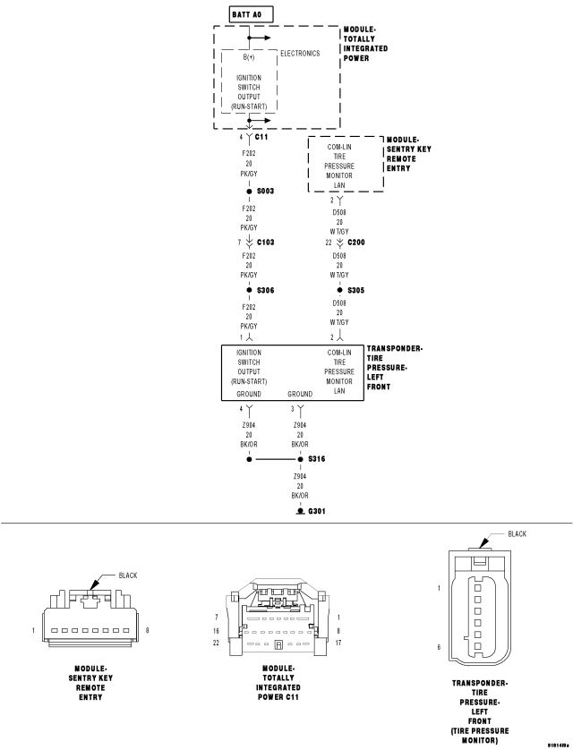
For a complete wiring diagram Refer to Section 8W.
- When Monitored:
- With the ignition on
- Battery voltage between 10 and 16 volts
- IOD fuse installed
- Set Condition:
If the WCM fails to receive bus messages from the Tire pressure trigger module for two consecutive counts of trigger module not responding to a communication check.
| Possible Causes |
| (D508) COM - LIN TIRE PRESSURE MONITOR LAN CIRCUIT SHORT TO VOLTAGE |
| (D508) COM - LIN TIRE PRESSURE MONITOR LAN CIRCUIT SHORT TO GROUND |
| (D508) COM - LIN TIRE PRESSURE MONITOR LAN CIRCUIT OPEN OR HIGH RESISTANCE |
| (F202) FUSED IGNITION SWITCH OUTPUT (RUN) CIRCUIT OPEN OR HIGH RESISTANCE |
| (Z904) GROUND CIRCUIT(S) OPEN OR HIGH RESISTANCE |
| (D508) COM-LIN TIRE PRESSURE MONITOR LAN CIRCUIT OPEN |
| TIRE PRESSURE TRIGGER MODULE POWER AND GROUND |
| WCM |
Diagnostic Test
1. VERIFY DTC IS ACTIVENOTE: Ensure the IOD fuse is installed and battery voltage is between 10 and 16 volts before proceeding.
Turn the ignition on.
With the scan tool, read and record WCM DTCs.
With the scan tool, erase WCM DTCs.
Cycle the ignition switch.
With the scan tool, read WCM DTCs.
Does this DTC reset?
Yes
- Go To 2
No
- Perform the Stored Lost Communication test procedure. Refer to the table of contents in this section. (Refer to 8 - ELECTRICAL/ELECTRONIC CONTROL MODULES - DIAGNOSIS AND TESTING).
- Perform BODY VERIFICATION TEST. (Refer to 8 - ELECTRICAL/ELECTRONIC CONTROL MODULES - STANDARD PROCEDURE).
2. (D508) COM-LIN TIRE PRESSURE MONITOR LAN CIRCUIT OPEN
Turn the ignition off.
Disconnect the Tire Pressure Trigger Module.
Disconnect the WCM.
With an ohmmeter measure the resistance of the (D508) COM-LIN TIRE PRESSURE MONITOR LAN CIRCUIT.
Is the resistance below 5 Ohms?
Yes
- Go To 3
No
- Repair or replace the open circuit.
- Perform TPM VERIFICATION TEST. (Refer to 22 - TIRES/WHEELS/TIRE PRESSURE MONITORING - STANDARD PROCEDURE)
3. (F202) FUSED IGNITION SWITCH OUTPUT (RUN) CIRCUIT OPEN OR HIGH RESISTANCE
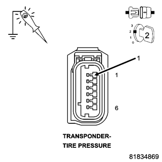
Turn the ignition off.
Disconnect the Tire Pressure Transponder harness connector.
Disconnect the Sentry Key Remote Entry Module harness connector.
Turn the ignition on.
Using a 12–volt test light connect to ground, check the (F202) Fused Ignition Switch Output (Run) circuit.
NOTE: The test light should be illuminated and bright. Compare the brightness to that of a direct connection to the battery.
Is the test light illuminated and bright?
Yes
- Go to 4
No
- Repair the (F202) Fused Ignition Switch Output (Run) circuit for an open circuit or high resistance.
- Perform TPM VERIFICATION TEST. (Refer to 22 - TIRES/WHEELS/TIRE PRESSURE MONITORING - STANDARD PROCEDURE)
4. (Z904) GROUND CIRCUIT(S) OPEN OR HIGH RESISTANCE
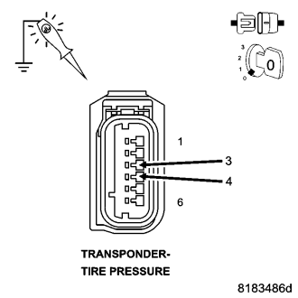
Using a 12-volt test light connect to battery voltage, probe each of the (Z904) Ground circuit(s).
NOTE: The test light should be illuminated and bright. Compare the brightness to that of a direct connection to the battery.
Does the test light illuminate brightly?
Yes
- Go to 5
No
- Repair the (Z904) Ground circuit(s) for an open circuit or high resistance.
- Perform TPM VERIFICATION TEST. (Refer to 22 - TIRES/WHEELS/TIRE PRESSURE MONITORING - STANDARD PROCEDURE)
5. (D508) COM - LIN TIRE PRESSURE MONITOR LAN CIRCUIT SHORT TO VOLTAGE
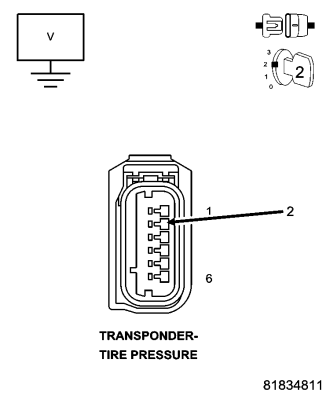
Turn the ignition on.
Measure the voltage of the (D508) COM - LIN Tire Pressure Monitor LAN circuit.
Is there any voltage present?
Yes
- Repair the (D508) COM - LIN Tire Pressure Monitor LAN circuit for a short to voltage.
No
- Go to 6
- Perform TPM VERIFICATION TEST. (Refer to 22 - TIRES/WHEELS/TIRE PRESSURE MONITORING - STANDARD PROCEDURE)
6. (D508) COM - LIN TIRE PRESSURE MONITOR LAN CIRCUIT SHORT TO GROUND
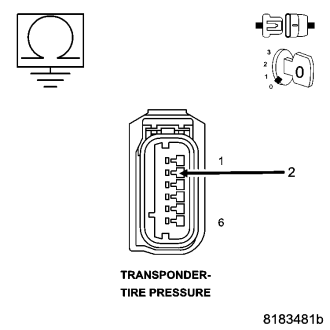
Turn the ignition off.
Measure the resistance between ground and the (D508) COM - LIN Tire Pressure Monitor LAN circuit.
Is the resistance below 5.0 ohms?
Yes
- Repair the (D508) COM - LIN Tire Pressure Monitor LAN circuit for a short to ground.
- Perform TPM VERIFICATION TEST. (Refer to 22 - TIRES/WHEELS/TIRE PRESSURE MONITORING - STANDARD PROCEDURE)
No
- Go to 7
7. (D508) COM - LIN TIRE PRESSURE MONITOR LAN CIRCUIT OPEN OR HIGH RESISTANCE
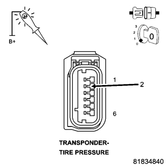
Use a jumper wire with one end connected to ground and the other to the (D508) COM - LIN Tire Pressure Monitor LAN circuit in the Front Left Pressure Tire Transponder harness connector.
Using a 12-Volt test light connected to battery voltage, probe the (D508) COM - LIN Tire Pressure Monitor LAN circuit in the TPM harness connector.
NOTE: The test light should be illuminated and bright. Compared the brightness to that of a direct connection to the battery.
Does the test light illuminate bright?
Yes
- Go to 8
No
- Repair the (D508) COM - LIN Tire Pressure Monitor LAN circuit for an open circuit or high resistance.
- Perform TPM VERIFICATION TEST. (Refer to 22 - TIRES/WHEELS/TIRE PRESSURE MONITORING - STANDARD PROCEDURE)
8. POWER AND GROUND CIRCUIT OPEN
Turn the ignition on.
With a voltmeter measure the voltage between the power and ground circuit at the Trigger Module.
Is the voltage at least the same as battery voltage?
Yes
- Go To 9
No
- Repair the open circuit.
- Perform TPM VERIFICATION TEST. (Refer to 22 - TIRES/WHEELS/TIRE PRESSURE MONITORING - STANDARD PROCEDURE)
9. CHECK FOR ADDITIONAL TRIGGER MODULE COMMUNICATION RELATED DTCs
With the scan tool, select Network View and select Advanced.
Is there more than one module with active DTCs “Logged Against” the WCM?
Yes
- Replace/update the WCM in accordance with the service information.
- Perform TPM VERIFICATION TEST. (Refer to 22 - TIRES/WHEELS/TIRE PRESSURE MONITORING - STANDARD PROCEDURE)
No
- Replace the Tire pressure trigger Module in accordance with the service information.
- Perform TPM VERIFICATION TEST. (Refer to 22 - TIRES/WHEELS/TIRE PRESSURE MONITORING - STANDARD PROCEDURE)