CHECK VALVE
DESCRIPTION
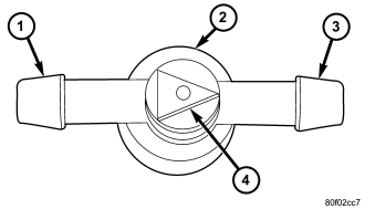
The rear check valve (2) connects the liftgate washer hose to the headliner washer hose and is located near the upper liftgate opening header behind the right D-pillar trim panel within the passenger compartment. The check valve consists of a molded plastic valve body with a raised arrowhead (4) molded into its center section indicating the direction of the flow through the valve. A barbed hose nipple (1 and 3) is formed on each side of the raised center section of the valve body. Within the check valve body, a small diaphragm is held against the lip of an integral sump well by a small plastic piston and a coiled spring.
The rear check valve cannot be adjusted or repaired and, if ineffective or damaged, it must be replaced.
OPERATION
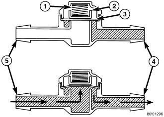
The rear check valve provides more than one function in this application. It prevents washer fluid from draining out of the rear washer supply hoses back to the washer reservoir. This drain-back would result in a lengthy delay from when the rear washer switch is actuated until washer fluid was dispensed through the rear washer nozzle, because the washer pump would have to refill the rear washer plumbing from the reservoir to the nozzle. Such a drain-back condition could also result in water, dirt, or other outside contaminants being siphoned into the washer system through the washer nozzle orifice. This water could subsequently freeze and plug the nozzle, while other contaminants could interfere with proper nozzle operation and cause improper nozzle spray patterns. In addition, the rear check valve prevents washer fluid from siphoning out through the rear washer nozzle after the rear washer system is turned OFF.
When the washer pump pressurizes and pumps washer fluid from the reservoir through the rear washer plumbing (5), the fluid pressure unseats a diaphragm (3) from over a sump well within the valve by overriding the pressure applied to it by a piston (2) and coiled spring (1). With the diaphragm unseated, washer fluid is allowed to flow toward the rear washer nozzle (4). When the washer pump stops operating, the spring pressure on the piston seats the diaphragm over the sump well in the valve and fluid flow in either direction within the rear washer plumbing is prevented.
REMOVAL
1. Disconnect and isolate the battery negative cable.
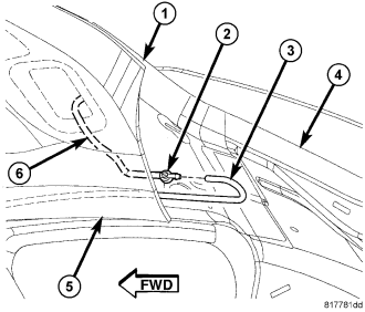
2. Partially remove the quarter trim from the right upper D-pillar (4). (Refer to 23 - BODY/INTERIOR/QUARTER PANEL TRIM - REMOVAL).
3. Pull the headliner (5) away from the upper liftgate opening header (1) far enough to access and disconnect the liftgate washer supply hose (6) and the headliner washer supply hose (3) from the barbed nipple on each side of the check valve (2).
4. Remove the check valve.
INSTALLATION
1. Position the rear check valve (2) between the upper liftgate opening header (1) and the headliner (5). Be certain that the raised arrow that indicates the flow direction on the center section of the valve is pointed toward the liftgate washer supply hose (6).
2. Reconnect the liftgate washer supply hose and the headliner washer supply hose (3) to the barbed nipples of the valve.
3. Reinstall the quarter trim onto the right upper D-pillar (4). (Refer to 23 - BODY/INTERIOR/QUARTER PANEL TRIM - INSTALLATION).
4. Reconnect the battery negative cable.