U0002-CAN C BUS OFF PERFORMANCE
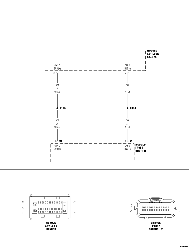
For a complete wiring diagram Refer to Section 8W.
- When Monitored:
With the ignition on.
- Set Condition:
The ABM detects a CAN Bus off event.
| Possible Causes |
| (D65) CAN C BUS (+) CIRCUIT SHORTED TO GROUND |
| (D64) CAN C BUS (-) CIRCUIT SHORTED TO GROUND |
| (D65) CAN C BUS (+) CIRCUIT SHORTED TO VOLTAGE |
| (D64) CAN C BUS (-) CIRCUIT SHORTED TO VOLTAGE |
| (D65) CAN C BUS (+) CIRCUIT SHORTED TO (D64) CAN C BUS (-) CIRCUIT |
| ANTI-LOCK BRAKE MODULE |
| POWERTRAIN CONTROL MODULE |
| SHIFTER LEVER ASSEMBLY (NAG1 ONLY) |
| TRANSMISSION CONTROL MODULE (NAG1 ONLY) |
| STEERING CONTROL MODULE |
| FRONT CONTROL MODULE |
Diagnostic Test
1. TEST FOR INTERMITTENT CONDITIONTurn the ignition on.
With the scan tool, record and erase FCM DTCs.
Cycle the ignition from on to off 3 times.
Turn the ignition on.
With the scan tool, read active FCM DTCs.
Does the scan tool display U0002-CAN C BUS OFF PERFORMANCE as active?
Yes
- Go To 2
No
- The conditions that caused this code to set are not present at this time. Using the wiring diagram/schematic as a guide, inspect the wiring and connectors.
- Refer to the ABS-INTERMITTENT CONDITION TEST. (Refer to 5 - BRAKES - DIAGNOSIS AND TESTING)
2. ANTI-LOCK BRAKE MODULE — INTERNAL SHORT
Turn the ignition off.
Disconnect the Anti-Lock Brake Module harness connector.
Turn the ignition on.
With the scan tool, record and erase FCM DTCs.
Cycle the ignition from on to off 3 times.
Turn the ignition on.
With the scan tool, read active FCM DTCs.
Does the scan tool display U0002-CAN C BUS OFF PERFORMANCE as active?
Yes
- Go To 3
No
- Inspect the wiring and connectors for damage or shorted circuits. If ok, replace the Antilock Brake Module in accordance with the service information.
- Perform ABS VERIFICATION TEST. (Refer to 5 - BRAKES - STANDARD PROCEDURE).
3. POWERTRAIN CONTROL MODULE — INTERNAL SHORT
Turn the ignition off.
Disconnect the Powertrain Control Module C1 harness connector.
Turn the ignition on.
With the scan tool, record and erase FCM DTCs.
Cycle the ignition from on to off 3 times.
Turn the ignition on.
With the scan tool, read active FCM DTCs.
Does the scan tool display U0002-CAN C BUS OFF PERFORMANCE as active?
Yes
- Go To 4
No
- Inspect the wiring and connectors for damage or shorted circuits. If ok, replace and program the Powertrain Control Module in accordance with the service information.
- Perform (NGC) POWERTRAIN VERIFICATION TEST VER - 5.
4. SHIFTER LEVER ASSEMBLY (NAG1 ONLY)— INTERNAL SHORT
Turn the ignition off.
NOTE: If the vehicle is not equipped with a NAG1 controller then skip this step.
Disconnect the Shifter Lever Assembly harness connector.
Turn the ignition on.
With the scan tool, record and erase FCM DTCs.
Cycle the ignition from on to off 3 times.
Turn the ignition on.
With the scan tool, read active FCM DTCs.
Does the scan tool display U0002-CAN C BUS OFF PERFORMANCE as active?
Yes
- Go To 5
No
- Inspect the wiring and connectors for damage or shorted circuits. If ok, replace and program the Shifter Lever Assembly in accordance with the service information.
- Perform NAG1 TRANSMISSION VERIFICATION TEST.
5. TRANSMISSION CONTROL MODULE (NAG1 ONLY)— INTERNAL SHORT
Turn the ignition off.
NOTE: If the vehicle is not equipped with a NAG1 controller then skip this step.
Disconnect the Transmission Control Module C2 harness connector.
Turn the ignition on.
With the scan tool, record and erase FCM DTCs.
Cycle the ignition from on to off 3 times.
Turn the ignition on.
With the scan tool, read active FCM DTCs.
Does the scan tool display U0002-CAN C BUS OFF PERFORMANCE as active?
Yes
- Go To 6
No
- Inspect the wiring and connectors for damage or shorted circuits. If ok, replace and program the Transmission Control Module in accordance with the service information.
- Perform NAG1 TRANSMISSION VERIFICATION TEST - VER 1.
6. STEERING CONTROL MODULE — INTERNAL SHORT
Turn the ignition off.
Disconnect the Steering Control Module harness connector.
Turn the ignition on.
With the scan tool, record and erase FCM DTCs.
Cycle the ignition from on to off 3 times.
Turn the ignition on.
With the scan tool, read active FCM DTCs.
Does the scan tool display U0002-CAN C BUS OFF PERFORMANCE as active?
Yes
- Go To 7
No
- Inspect the wiring and connectors for damage or shorted circuits. If ok, replace and program the Steering Control Module in accordance with the service information.
- Perform BODY VERIFICATION TEST - VER 1.
7. (D65) CAN C BUS (+) CIRCUIT SHORTED TO VOLTAGE
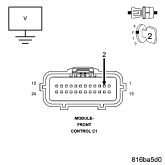
Turn the ignition off.
Disconnect the Front Control Module C1 harness connector.
Turn the ignition on.
Measure the voltage between the (D65) CAN C Bus (+) circuit and ground.
Is there any voltage present?
Yes
- Repair the (D65) CAN C Bus (+) circuit for a short to voltage.
- Perform BODY VERIFICATION TEST - VER 1.
No
- Go To 8
8. (D64) CAN C BUS (-) CIRCUIT SHORTED TO VOLTAGE
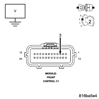
Measure the voltage between the (D64) CAN C Bus (-) circuit and ground.
Is there any voltage present?
Yes
- Repair the (D64) CAN C Bus (-) circuit for a short to voltage.
- Perform BODY VERIFICATION TEST - VER 1.
No
- Go To 9
9. (D65) CAN C BUS (+) CIRCUIT SHORTED TO GROUND
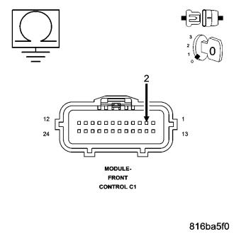
Turn the ignition off.
Measure the resistance between ground and the (D65) CAN C Bus (+) circuit.
Is any resistance present?
Yes
- Repair the (D65) CAN C Bus (+) circuit for a short to ground.
- Perform BODY VERIFICATION TEST - VER 1.
No
- Go To 10
10. (D64) CAN C BUS (-) CIRCUIT SHORTED TO GROUND
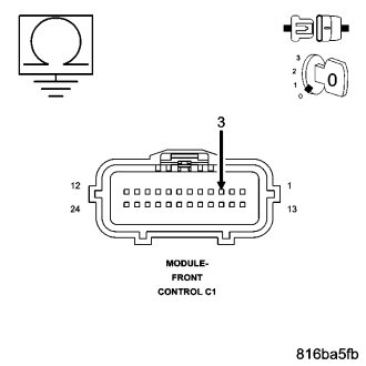
Measure the resistance between ground and the (D64) CAN C Bus (-) circuit.
Is any resistance present?
Yes
- Repair the (D64) CAN C Bus (-) circuit for a short to ground.
- Perform BODY VERIFICATION TEST - VER 1.
No
- Go To 11
11. (D65) CAN C BUS (+) CIRCUIT SHORTED TO (D64) CAN C BUS (-) CIRCUIT
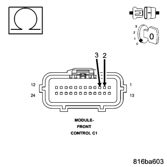
Measure the resistance between the (D65) CAN C Bus (+) circuit and the (D64) CAN C Bus (-) circuit.
Is any resistance present?
Yes
- Repair the (D65) CAN C Bus (+) circuit for a short to the (D64) CAN C Bus (-) circuit.
- Perform BODY VERIFICATION TEST - VER 1.
No
- Inspect the wiring and connectors for damage or shorted circuits. If ok, replace and program the Front Control Module in accordance with the service information.
- Perform BODY VERIFICATION TEST - VER 1.