DIAGNOSIS AND TESTING
- B1D4F-ADJUSTABLE PEDAL INHIBIT CIRCUIT LOW
- B1D50-ADJUSTABLE PEDAL INHIBIT CIRCUIT HIGH
- B1D51-ADJUSTABLE PEDAL INHIBIT CIRCUIT OPEN
- B1D56-ADJUSTABLE PEDAL SENSOR CIRCUIT LOW
- B1D57-ADJUSTABLE PEDAL SENSOR CIRCUIT HIGH
- B1D5B-ADJUSTABLE PEDAL SWITCH CIRCUIT PERFORMANCE
- B1D5C-ADJUSTABLE PEDAL SWITCH CIRCUIT STUCK FORWARD
- B1D5D-ADJUSTABLE PEDAL SWITCH CIRCUIT STUCK REARWARD
- B1D67-ADJUSTABLE PEDAL CONTROL CIRCUIT PERFORMANCE
- APS-INTERMITTENT CONDITION TEST
B1D4F-ADJUSTABLE PEDAL INHIBIT CIRCUIT LOW
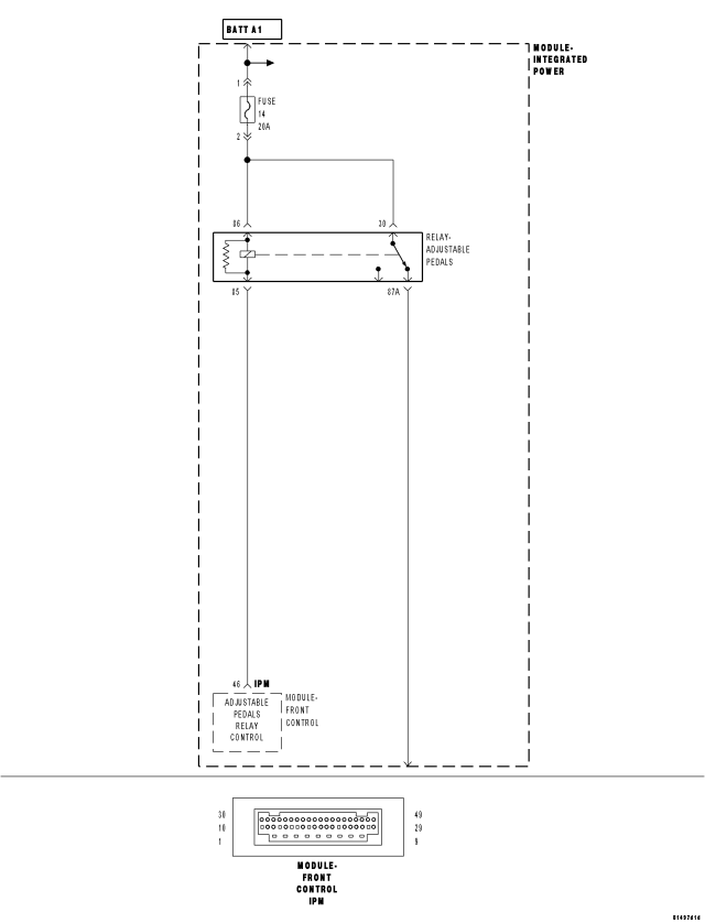
For a complete wiring diagram Refer to Section 8W.
- When Monitored:
With the ignition on.
- Set Condition:
When the Front Control Module fails the Adjustable Pedal Inhibit Relay circuit.
| Possible Causes |
| TERMINAL/CONNECTOR DAMAGE |
| ADJUSTABLE PEDALS RELAY |
| ADJUSTABLE PEDALS RELAY CONTROL CIRCUIT SHORTED TO VOLTAGE, GROUND, OR OPEN |
| FRONT CONTROL MODULE |
| INTEGRATED POWER MODULE |
Diagnostic Test
1. CHECK FOR A DTC B1D4F-ADJUSTABLE PEDAL INHIBIT CIRCUIT LOWNOTE: This DTC must be active for the results of this test to be valid.
Turn the ignition on.
With the scan tool, read and record DTCs.
With the scan tool, read and record Freeze Frame information.
With the scan tool, erase DTCs.
Cycle the ignition switch from off to on.
WARNING: Apply the parking brake. The vehicle may roll when the Transmission is shifted out of Park.
Shift into Reverse for at least 5 seconds, then move the shifter back into Park.
With the scan tool, read and record DTCs.
Does the scan tool display: B1D4F-ADJUSTABLE PEDAL INHIBIT CIRCUIT LOW?
Yes
- Go To 2
No
- The condition that caused the symptom is currently not present. Inspect the related wiring for a possible intermittent condition. Look for any chafed, pierced, pinched, or partially broken wires.
- Refer to the APS-INTERMITTENT CONDITION TEST. (Refer to 5 - BRAKES/ELECTRICAL - DIAGNOSIS AND TESTING).
2. CHECK THE TERMINALS/CONNECTORS FOR DAMAGE
NOTE: Check all related wiring for bruised, chafed, pierced, or partially broken wires.
NOTE: Check all related connectors for broken, bent, pushed out, or corroded terminals.
Turn the ignition off.
Visually inspect the wiring for damage.
Were any problems found?
Yes
- Repair as necessary.
- Perform APS VERIFICATION TEST. (Refer to 5 - BRAKES/ELECTRICAL - STANDARD PROCEDURE).
No
- Go To 3
3. FUSED B+ CIRCUIT OPEN OR HIGH RESISTANCE (IPM)
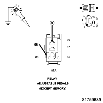
Using a 12–volt test light connect to ground, check the internal Fused B(+) circuits at the Adjustable Pedals Relay connector of the IPM.
NOTE: The test light should be illuminated and bright. Compare the brightness to that of a direct connection to the battery.
Is the test light illuminated and bright for both circuits?
Yes
- Go To 4
No
- Remove and inspect Fuse in the IPM. If the fuse is open, test the circuit for a short to ground. Repair as necessary. If the fuse is OK, replace the Integrated Power Module in accordance with the Service Information.
- Perform APS VERIFICATION TEST. (Refer to 5 - BRAKES/ELECTRICAL - STANDARD PROCEDURE).
4. CHECK THE ADJUSTABLE PEDALS RELAY OUTPUT VOLTAGE
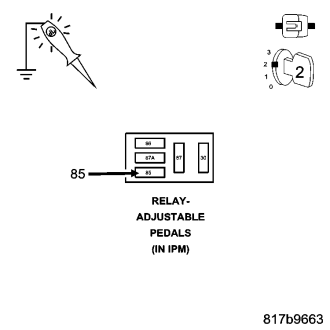
Turn the ignition on.
Using a 12-volt test light connected to ground, check the Adjustable Pedals Relay Control circuit.
Does the test light illuminate brightly?
Yes
- Go To 5
No
- Replace the Adjustable Pedals Relay in accordance with the Service Information.
- Perform APS VERIFICATION TEST. (Refer to 5 - BRAKES/ELECTRICAL - STANDARD PROCEDURE).
5. CHECK THE ADJUSTABLE PEDALS RELAY CONTROL CIRCUIT FOR VOLTAGE
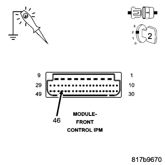
Turn the ignition on.
Using a 12-volt test light connected to ground, disconnect the Front Control Module harness connector and check the Adjustable Pedals Relay Control circuit at the Front Control Module connector.
Does the test light illuminate?
Yes
- Go To 6
No
- Repair the Adjustable Pedals Relay Control circuit for a open or high resistance.
- Perform APS VERIFICATION TEST. (Refer to 5 - BRAKES/ELECTRICAL - STANDARD PROCEDURE).
6. FRONT CONTROL MODULE
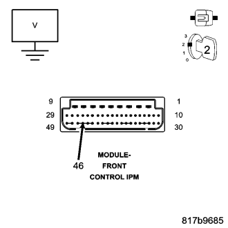
Reconnect all components.
Turn the ignition on.
With the scan tool, actuate the Adjustable Pedals Relay.
Measure the voltage of the Adjustable Pedals Relay Control circuit at the Front Control Module connector of the IPM while back probing connector.
NOTE: With the Relay actuated ON, the circuit voltage should be 0 volts.
NOTE: With the Relay actuated OFF, the circuit voltage should be approximately 2.5 volts.
Does the circuit voltage display as described during the actuation test?
Yes
- Replace the Adjustable Pedals Relay in accordance with the Service Information.
- Perform APS VERIFICATION TEST. (Refer to 5 - BRAKES/ELECTRICAL - STANDARD PROCEDURE).
No
- Replace the Front Control Module in accordance with the Service Information.
- Perform APS VERIFICATION TEST. (Refer to 5 - BRAKES/ELECTRICAL - STANDARD PROCEDURE).
B1D50-ADJUSTABLE PEDAL INHIBIT CIRCUIT HIGH
For a complete wiring diagram Refer to Section 8W.
- When Monitored:
With the ignition on.
- Set Condition:
When the Front Control Module fails the Adjustable Pedal Inhibit Relay circuit.
| Possible Causes |
| TERMINAL/CONNECTOR DAMAGE |
| ADJUSTABLE PEDALS RELAY |
| ADJUSTABLE PEDALS RELAY CONTROL CIRCUIT SHORTED TO VOLTAGE, GROUND, OR OPEN |
| FRONT CONTROL MODULE |
| INTEGRATED POWER MODULE |
Diagnostic Test
1. CHECK FOR A DTC B1D50-ADJUSTABLE PEDAL INHIBIT CIRCUIT HIGHNOTE: This DTC must be active for the results of this test to be valid.
Turn the ignition on.
With the scan tool, read and record DTCs.
With the scan tool, read and record Freeze Frame information.
With the scan tool, erase DTCs.
Cycle the ignition switch from off to on.
With the scan tool, read and record DTCs.
Does the scan tool display: B1D50-ADJUSTABLE PEDAL INHIBIT CIRCUIT HIGH?
Yes
- Go To 2
No
- The condition that caused the symptom is currently not present. Inspect the related wiring for a possible intermittent condition. Look for any chafed, pierced, pinched, or partially broken wires.
- Refer to the APS-INTERMITTENT CONDITION TEST. (Refer to 5 - BRAKES/ELECTRICAL - DIAGNOSIS AND TESTING).
2. CHECK THE TERMINALS/CONNECTORS FOR DAMAGE
NOTE: Check all related wiring for bruised, chafed, pierced, or partially broken wires.
NOTE: Check all related connectors for broken, bent, pushed out, or corroded terminals.
Turn the ignition off.
Visually inspect the wiring for damage.
Were any problems found?
Yes
- Repair as necessary.
- Perform APS VERIFICATION TEST. (Refer to 5 - BRAKES/ELECTRICAL - STANDARD PROCEDURE).
No
- Go To 3
3. SWAP OUT THE ADJUSTABLE PEDALS RELAY
Install a known good relay in place of the Adjustable Pedals Relay.
Turn the ignition on.
With the scan tool, erase DTC's.
Cycle the ignition switch from off to on.
With the scan tool, read and record DTC's
Does the scan tool display: B1D4F-ADJUSTABLE PEDAL INHIBIT CIRCUIT LOW?
Yes
- Go To 4
No
- Replace the Adjustable Pedals Relay in accordance with the Service Information.
- Perform APS VERIFICATION TEST. (Refer to 5 - BRAKES/ELECTRICAL - STANDARD PROCEDURE).
4. CHECK THE VOLTAGE ON THE FUSED B(+) CIRCUIT FOR THE ADJUSTABLE PEDALS RELAY
Turn the ignition off.
Remove the Adjustable Pedals Relay from the IPM.
Measure the voltage of the internal Fused B(+) circuit at the IPM.
Is the voltage above 10 volts?
Yes
- Go To 5
No
- Replace the IPM in accordance with the Service Information.
- Perform APS VERIFICATION TEST. (Refer to 5 - BRAKES/ELECTRICAL - STANDARD PROCEDURE).
5. CHECK THE ADJUSTABLE PEDALS RELAY CONTROL CIRCUIT FOR A SHORT TO GROUND
Disconnect the Front Control Module harness connector.
Using a 12-volt test light connected to 12-volts, check the Adjustable Pedals Relay Control circuit.
Does the test light illuminate brightly?
Yes
- Repair the Adjustable Pedals Relay Control circuit for a short to ground.
- Perform APS VERIFICATION TEST. (Refer to 5 - BRAKES/ELECTRICAL - STANDARD PROCEDURE).
No
- Go To 6
6. CHECK THE ADJUSTABLE PEDALS RELAY CONTROL CIRCUIT FOR A SHORT TO VOLTAGE
Turn the ignition on.
Using a 12-volt test light connected to ground, check the Adjustable Pedals Relay Control circuit.
Does the test light illuminate brightly?
Yes
- Repair the Adjustable Pedals Relay Control circuit for a short to voltage.
- Perform APS VERIFICATION TEST. (Refer to 5 - BRAKES/ELECTRICAL - STANDARD PROCEDURE).
No
- Go To 7
7. CHECK THE ADJUSTABLE PEDALS RELAY CONTROL CIRCUIT FOR AN OPEN
Turn the ignition off.
Connect a jumper wire between the Adjustable Pedals Relay Control circuit and ground.
Using a 12-volt test light connected to 12-volts, check the Adjustable Pedals Relay Control circuit.
Does the test light illuminate brightly
Yes
- Replace the Front Control Module in accordance with the Service Information.
- Perform APS VERIFICATION TEST. (Refer to 5 - BRAKES/ELECTRICAL - STANDARD PROCEDURE).
No
- Repair the Adjustable Pedals Relay Control circuit for an open.
- Perform APS VERIFICATION TEST. (Refer to 5 - BRAKES/ELECTRICAL - STANDARD PROCEDURE).
B1D51-ADJUSTABLE PEDAL INHIBIT CIRCUIT OPEN
For a complete wiring diagram Refer to Section 8W.
- When Monitored:
With the ignition on.
- Set Condition:
When the Front Control Module fails the Adjustable Pedal Inhibit Relay circuit.
| Possible Causes |
| TERMINAL/CONNECTOR DAMAGE |
| ADJUSTABLE PEDALS RELAY |
| ADJUSTABLE PEDALS RELAY CONTROL CIRCUIT SHORTED TO VOLTAGE, GROUND, OR OPEN |
| FRONT CONTROL MODULE |
| INTEGRATED POWER MODULE |
Diagnostic Test
1. CHECK FOR A DTC B1D51-ADJUSTABLE PEDAL INHIBIT CIRCUIT OPENNOTE: This DTC must be active for the results of this test to be valid.
Turn the ignition on.
With the scan tool, read and record DTCs.
With the scan tool, read and record Freeze Frame information.
With the scan tool, erase DTCs.
Cycle the ignition switch from off to on.
With the scan tool, read and record DTCs.
Does the scan tool display:B1D51-ADJUSTABLE PEDAL INHIBIT CIRCUIT OPEN?
Yes
- Go To 2
No
- The condition that caused the symptom is currently not present. Inspect the related wiring for a possible intermittent condition. Look for any chafed, pierced, pinched, or partially broken wires.
- Refer to the APS-INTERMITTENT CONDITION TEST. (Refer to 5 - BRAKES/ELECTRICAL - DIAGNOSIS AND TESTING).
2. CHECK THE TERMINALS/CONNECTORS FOR DAMAGE
NOTE: Check all related wiring for bruised, chafed, pierced, or partially broken wires.
NOTE: Check all related connectors for broken, bent, pushed out, or corroded terminals.
Turn the ignition off.
Visually inspect the wiring for damage.
Were any problems found?
Yes
- Repair as necessary.
- Perform APS VERIFICATION TEST. (Refer to 5 - BRAKES/ELECTRICAL - STANDARD PROCEDURE).
No
- Go To 3
3. SWAP OUT THE ADJUSTABLE PEDALS RELAY
Install a known good relay in place of the Adjustable Pedals Relay.
Turn the ignition on.
With the scan tool, erase DTC's.
Cycle the ignition switch from off to on.
With the scan tool, read and record DTC's
Does the scan tool display: B1D4F-ADJUSTABLE PEDAL INHIBIT CIRCUIT LOW?
Yes
- Go To 4
No
- Replace the Adjustable Pedals Relay in accordance with the Service Information.
- Perform APS VERIFICATION TEST. (Refer to 5 - BRAKES/ELECTRICAL - STANDARD PROCEDURE).
4. CHECK THE VOLTAGE ON THE FUSED B(+) CIRCUIT FOR THE ADJUSTABLE PEDALS RELAY
Turn the ignition off.
Remove the Adjustable Pedals Relay from the IPM.
Measure the voltage of the internal Fused B(+) circuit at the IPM.
Is the voltage above 10 volts?
Yes
- Go To 5
No
- Replace the IPM in accordance with the Service Information.
- Perform APS VERIFICATION TEST. (Refer to 5 - BRAKES/ELECTRICAL - STANDARD PROCEDURE).
5. CHECK THE ADJUSTABLE PEDALS RELAY CONTROL CIRCUIT FOR A SHORT TO GROUND
Disconnect the Front Control Module harness connector.
Using a 12-volt test light connected to 12-volts, check the Adjustable Pedals Relay Control circuit.
Does the test light illuminate brightly?
Yes
- Repair the Adjustable Pedals Relay Control circuit for a short to ground.
- Perform APS VERIFICATION TEST. (Refer to 5 - BRAKES/ELECTRICAL - STANDARD PROCEDURE).
No
- Go To 6
6. CHECK THE ADJUSTABLE PEDALS RELAY CONTROL CIRCUIT FOR A SHORT TO VOLTAGE
Turn the ignition on.
Using a 12-volt test light connected to ground, check the Adjustable Pedals Relay Control circuit.
Does the test light illuminate brightly?
Yes
- Repair the Adjustable Pedals Relay Control circuit for a short to voltage.
- Perform APS VERIFICATION TEST. (Refer to 5 - BRAKES/ELECTRICAL - STANDARD PROCEDURE).
No
- Go To 7
7. CHECK THE ADJUSTABLE PEDALS RELAY CONTROL CIRCUIT FOR AN OPEN
Turn the ignition off.
Connect a jumper wire between the Adjustable Pedals Relay Control circuit and ground.
Using a 12-volt test light connected to 12-volts, check the Adjustable Pedals Relay Control circuit.
Does the test light illuminate brightly
Yes
- Replace the Front Control Module in accordance with the Service Information.
- Perform APS VERIFICATION TEST. (Refer to 5 - BRAKES/ELECTRICAL - STANDARD PROCEDURE).
No
- Repair the (P201) Adjustable Pedals Relay Control circuit for an open.
- Perform APS VERIFICATION TEST. (Refer to 5 - BRAKES/ELECTRICAL - STANDARD PROCEDURE).
B1D56-ADJUSTABLE PEDAL SENSOR CIRCUIT LOW
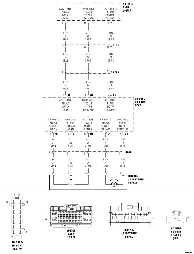
For a complete wiring diagram Refer to Section 8W.
- When Monitored:
The Adjustable Pedal Motor is in active operation.
- Set Condition:
The Memory Seat Module detects a low signal circuit voltage that is not within voltage specification from the Adjustable Pedal Sensor.
| Possible Causes |
| CONNECTOR/TERMINAL DAMAGE |
| (G11) ADJUSTABLE PEDALS SENSOR SUPPLY CIRCUIT SHORTED TO GROUND, OR OPEN |
| (G12) ADJUSTABLE PEDALS SENSOR SIGNAL CIRCUIT SHORTED TO GROUND, OR OPEN |
| ADJUSTABLE PEDALS SENSOR - INTERNAL FAULT |
| MEMORY SEAT MODULE - INTERNAL FAULT |
Diagnostic Test
1. CHECK FOR DTC B1D56–ADJUSTABLE PEDAL SENSOR CIRCUIT LOWNOTE: This DTC must be active for the results of this test to be valid.
Turn the ignition on.
With the scan tool, record and erase DTCs.
Cycle the ignition switch from off to on.
Cycle the Adjustable Pedals Switch forward and rearward.
With the scan tool, read DTCs.
Does the scan tool display: B1D56–ADJUSTABLE PEDAL SENSOR CIRCUIT LOW?
Yes
- Go To 2
No
- The condition that caused the symptom is currently not present. Inspect the related wiring for a possible intermittent condition. Look for any chafed, pierced, pinched, or partially broken wires.
- Refer to the APS-INTERMITTENT CONDITION TEST. (Refer to 5 - BRAKES/ELECTRICAL - DIAGNOSIS AND TESTING).
2. CHECK CONNECTOR/TERMINAL FOR DAMAGE
NOTE: Check all terminals for broken, bent, pushed out, or corroded terminals.
Turn the ignition off.
Inspect the Memory Seat Module harness connector and Adjustable Pedals Motor harness connector.
Is there any connector or terminal damaged?
Yes
- Repair as necessary.
- Perform APS VERIFICATION TEST. (Refer to 5 - BRAKES/ELECTRICAL - STANDARD PROCEDURE).
No
- Go To 3
3. CHECK (G11) ADJUSTABLE PEDALS SENSOR SUPPLY CIRCUIT FOR A SHORT TO GROUND
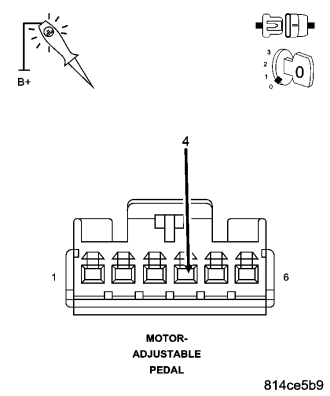
Disconnect the Memory Seat Module harness connector.
Disconnect the Adjustable Pedals Motor harness connector.
Using a 12-volt test light connected to 12-volts, probe the (G11) Adjustable Pedals Sensor Supply circuit.
Does the test light illuminate brightly?
Yes
- Repair the (G11) Adjustable Pedals Sensor Supply circuit for a short to ground.
- Perform APS VERIFICATION TEST. (Refer to 5 - BRAKES/ELECTRICAL - STANDARD PROCEDURE).
No
- Go To 4
4. CHECK (G11) ADJUSTABLE PEDALS SENSOR SUPPLY CIRCUIT FOR AN OPEN
Connect a jumper wire between the (G11) Adjustable Pedals Sensor Supply circuit and ground at the Memory Seat Module harness connector.
Using a 12-volt test light connected to 12-volts, probe the (G11) Adjustable Pedals Sensor Supply circuit.
Does the test light illuminate brightly
Yes
- Go To 5
No
- Repair the (G11) Adjustable Pedals Sensor Supply circuit for an open.
- Perform APS VERIFICATION TEST. (Refer to 5 - BRAKES/ELECTRICAL - STANDARD PROCEDURE).
5. CHECK (G12) ADJUSTABLE PEDALS SENSOR SIGNAL CIRCUIT FOR A SHORT TO GROUND
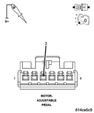
Using a 12-volt test light connected to 12-volts, probe the (G12) Adjustable Pedals Sensor Signal circuit.
Does the test light illuminate brightly?
Yes
- Repair the (G12) Adjustable Pedals Sensor Signal circuit for a short to ground.
- Perform APS VERIFICATION TEST. (Refer to 5 - BRAKES/ELECTRICAL - STANDARD PROCEDURE).
No
- Go To 6
6. CHECK (G12) ADJUSTABLE PEDALS SENSOR SIGNAL CIRCUIT FOR AN OPEN
Connect a jumper wire between the (G12) Adjustable Pedals Sensor Signal circuit and ground at the Memory Seat Module harness connector.
Using a 12-volt test light connected to 12-volts, probe the (G12) Adjustable Pedals Sensor Signal circuit.
Does the test light illuminate brightly?
Yes
- Go To 7
No
- Repair the (G12) Adjustable Pedals Sensor Signal circuit for an open.
- Perform APS VERIFICATION TEST. (Refer to 5 - BRAKES/ELECTRICAL - STANDARD PROCEDURE).
7. CHECK (G11) ADJUSTABLE PEDALS SENSOR SUPPLY CIRCUIT VOLTAGE
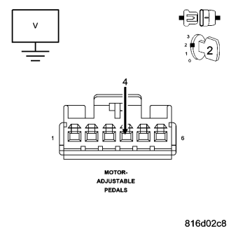
Connect the Memory Seat Module harness connector.
Turn the ignition on.
Measure the voltage between the (G11) Adjustable Pedals Sensor Supply circuit and ground at the Adjustable Pedal Motor harness connector.
Is the voltage between 4.0 and 5.2 volts?
Yes
- Go To 8
No
- Replace and reprogram the Memory Seat Module in accordance with the Service Information.
- Perform APS VERIFICATION TEST. (Refer to 5 - BRAKES/ELECTRICAL - STANDARD PROCEDURE).
8. CHECK (G12) ADJUSTABLE PEDALS SENSOR SIGNAL CIRCUIT VOLTAGE
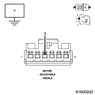
Measure the voltage of the (G12) Adjustable Pedals Sensor Signal circuit in the Memory Seat Module harness connector.
Is the voltage above 0.5 volts?
Yes
- Replace and reprogram the Memory Seat Module in accordance with the Service Information.
- Perform APS VERIFICATION TEST. (Refer to 5 - BRAKES/ELECTRICAL - STANDARD PROCEDURE).
No
- Replace the Adjustable Pedals Sensor in accordance with the Service Information.
- Perform APS VERIFICATION TEST. (Refer to 5 - BRAKES/ELECTRICAL - STANDARD PROCEDURE).
B1D57-ADJUSTABLE PEDAL SENSOR CIRCUIT HIGH
For a complete wiring diagram Refer to Section 8W.
- When Monitored:
The Adjustable Pedal Motor is in active operation.
- Set Condition:
The Memory Seat Module detects a high signal circuit voltage that is not within voltage specification from the Adjustable Pedal Sensor.
| Possible Causes |
| CONNECTOR/TERMINAL DAMAGE |
| (G11) ADJUSTABLE PEDALS SENSOR SUPPLY CIRCUIT SHORTED TO VOLTAGE |
| (G12) ADJUSTABLE PEDALS SENSOR SIGNAL CIRCUIT SHORTED TO VOLTAGE |
| (G912) ADJUSTABLE PEDALS SENSOR RETURN CIRCUIT OPEN |
| ADJUSTABLE PEDALS SENSOR - INTERNAL FAULT |
| MEMORY SEAT MODULE - INTERNAL FAULT |
Diagnostic Test
1. CHECK FOR DTC B1D57–ADJUSTABLE PEDAL SENSOR CIRCUIT HIGHNOTE: This DTC must be active for the results of this test to be valid.
Turn the ignition on.
With the scan tool, record and erase DTCs.
Cycle the ignition switch from off to on.
Cycle the Adjustable Pedals Switch forward and rearward.
With the scan tool, read DTCs.
Does the scan tool display: B1D57–ADJUSTABLE PEDAL SENSOR CIRCUIT HIGH?
Yes
- Go To 2
No
- The condition that caused the symptom is currently not present. Inspect the related wiring for a possible intermittent condition. Look for any chafed, pierced, pinched, or partially broken wires.
- Refer to the APS-INTERMITTENT CONDITION TEST. (Refer to 5 - BRAKES/ELECTRICAL - DIAGNOSIS AND TESTING).
2. CHECK CONNECTOR/TERMINAL FOR DAMAGE
NOTE: Check all terminals for broken, bent, pushed out, or corroded terminals.
Turn the ignition off.
Inspect the Memory Seat Module harness connector and the Adjustable Pedal Motor harness connector.
Is there any connector or terminal damaged?
Yes
- Repair as necessary.
- Perform APS VERIFICATION TEST. (Refer to 5 - BRAKES/ELECTRICAL - STANDARD PROCEDURE).
No
- Go To 3
3. CHECK (G11) ADJUSTABLE PEDALS SENSOR SUPPLY CIRCUIT FOR A SHORT TO VOLTAGE
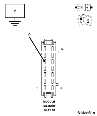
Disconnect the Memory Seat Module harness connector.
Disconnect the Adjustable Pedal Motor harness connector.
Turn the ignition on.
Measure the voltage between the (G11) Adjustable Pedals Sensor Supply circuit and ground.
Is voltage present?
Yes
- Repair the (G11) Adjustable Pedals Sensor Supply circuit for a short to voltage.
- Perform APS VERIFICATION TEST. (Refer to 5 - BRAKES/ELECTRICAL - STANDARD PROCEDURE).
No
- Go To 4
4. CHECK (G12) ADJUSTABLE PEDALS SENSOR SIGNAL CIRCUIT FOR A SHORT TO VOLTAGE
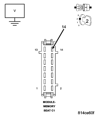
Measure the voltage between the (G12) Adjustable Pedals Sensor Signal circuit and ground.
Is voltage present?
Yes
- Repair the (G12) Adjustable Pedals Sensor Signal circuit for a short to voltage.
- Perform APS VERIFICATION TEST. (Refer to 5 - BRAKES/ELECTRICAL - STANDARD PROCEDURE).
No
- Go To 5
5. (G12) ADJUSTABLE PEDAL SENSOR SIGNAL SHORTED TO SENSOR SUPPLY
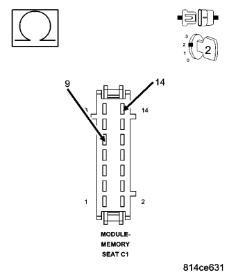
Turn ignition off.
Measure the resistance between the (G12) Adjustable Pedals Sensor Signal circuit and the Sensor Supply circuit.
Is the resistance below 100 ohms?
Yes
- Repair the (G12) Adjustable Pedals Sensor Signal circuit for a short to the Sensor Supply circuit.
- Perform APS VERIFICATION TEST. (Refer to 5 - BRAKES/ELECTRICAL - STANDARD PROCEDURE).
No
- Go To 6
6. (G912) ADJUSTABLE PEDALS SENSOR RETURN CIRCUIT OPEN
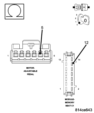
Measure the resistance of the (G912) Adjustable Pedals Sensor Return circuit between the Memory Seat Module harness connector and the Adjustable Pedal Motor harness connector.
Is the resistance below 5 ohms?
Yes
- Go To 7
No
- Repair the (G912) Adjustable Pedals Sensor Return circuit for an open.
- Perform APS VERIFICATION TEST. (Refer to 5 - BRAKES/ELECTRICAL - STANDARD PROCEDURE).
7. CHECK (G12) ADJUSTABLE PEDALS SENSOR SIGNAL CIRCUIT VOLTAGE
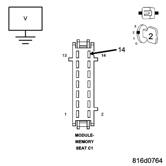
Turn the ignition off.
Reconnect the Adjustable Pedal Motor harness connector.
Turn the ignition on.
Measure the voltage of the (G12) Adjustable Pedals Sensor Signal circuit in the Memory Seat Module harness connector.
Is the voltage below 4.0 volts?
Yes
- Replace and reprogram the Memory Seat Module in accordance with the Service Information.
- Perform APS VERIFICATION TEST. (Refer to 5 - BRAKES/ELECTRICAL - STANDARD PROCEDURE).
No
- Replace the Adjustable Pedals Sensor in accordance with the Service Information.
- Perform APS VERIFICATION TEST. (Refer to 5 - BRAKES/ELECTRICAL - STANDARD PROCEDURE).
B1D5B-ADJUSTABLE PEDAL SWITCH CIRCUIT PERFORMANCE
For a complete wiring diagram Refer to Section 8W.
- When Monitored:
The Adjustable Pedals Switch is in active operation.
- Set Condition:
The Memory Seat Module detects an activation of both pedal switches at the same time.
| Possible Causes |
| CONNECTOR/TERMINAL DAMAGE |
| (Q103) ADJUSTABLE PEDALS SWITCH REARWARD CIRCUIT SHORTED TO GROUND |
| (Q102) ADJUSTABLE PEDALS SWITCH FORWARD CIRCUIT SHORTED TO GROUND |
| (Q103) ADJUSTABLE PEDALS SWITCH REARWARD CIRCUIT AND (Q102) ADJUSTABLE PEDALS SWITCH FORWARD CIRCUIT SHORTED TOGETHER |
| ADJUSTABLE PEDALS SWITCH - INTERNAL FAULT |
| MEMORY SEAT MODULE - INTERNAL FAULT |
Diagnostic Test
1. CHECK FOR DTC B1D5B–ADJUSTABLE PEDAL SWITCH CIRCUIT PERFORMANCENOTE: This DTC must be active for the results of this test to be valid.
Turn the ignition on.
With the scan tool, record and erase DTCs.
Cycle the ignition switch from off to on.
Cycle the Adjustable Pedals Switch forward and rearward.
With the scan tool, read DTCs.
Does the scan tool display: B1D5B–ADJUSTABLE PEDAL SWITCH CIRCUIT PERFORMANCE?
Yes
- Go To 2
No
- The condition that caused the symptom is currently not present. Inspect the related wiring for a possible intermittent condition. Look for any chafed, pierced, pinched, or partially broken wires.
- Refer to the APS-INTERMITTENT CONDITION TEST. (Refer to 5 - BRAKES/ELECTRICAL - DIAGNOSIS AND TESTING).
2. CHECK CONNECTOR/TERMINAL FOR DAMAGE
NOTE: Check all terminals for broken, bent, pushed out, or corroded terminals.
Turn the ignition off.
Inspect the Memory Seat Module harness connector and Lower Switch Bank harness connector.
Is the Lower Switch Bank or any of the connectors/terminals damaged?
Yes
- Repair as necessary.
- Perform APS VERIFICATION TEST. (Refer to 5 - BRAKES/ELECTRICAL - STANDARD PROCEDURE).
No
- Go To 3
3. CHECK (Q103) ADJUSTABLE PEDALS SWITCH REARWARD CIRCUIT FOR A SHORT TO GROUND
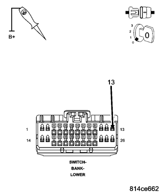
Turn the ignition off.
Disconnect the Memory Seat Module harness connector.
Disconnect the Lower Switch Bank harness connector.
Using a 12-volt test light connected to 12-volts, probe the (Q103) Adjustable Pedals Switch Rearward circuit.
Does the test light illuminate brightly?
Yes
- Repair the (Q103) Adjustable Pedals Switch Rearward circuit for a short to ground.
- Perform APS VERIFICATION TEST. (Refer to 5 - BRAKES/ELECTRICAL - STANDARD PROCEDURE).
No
- Go To 4
4. CHECK (Q102) ADJUSTABLE PEDALS SWITCH FORWARD CIRCUIT FOR A SHORT TO GROUND
Turn the ignition off.
Disconnect the Memory Seat Module harness connector.
Disconnect the Lower Switch Bank harness connector.
Using a 12-volt test light connected to 12-volts, probe the (Q102) Adjustable Pedals Switch Forward circuit.
Does the test light illuminate brightly?
Yes
- Repair the (Q102) Adjustable Pedals Switch Forward circuit for a short to ground.
- Perform APS VERIFICATION TEST. (Refer to 5 - BRAKES/ELECTRICAL - STANDARD PROCEDURE).
No
- Go To 5
5. CHECK (Q103) ADJUSTABLE PEDALS SWITCH REARWARD CIRCUIT AND ADJUSTABLE PEDALS SWITCH FORWARD CIRCUIT FOR A SHORT TOGETHER
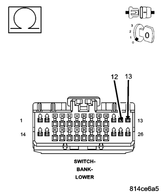
Turn the ignition off.
Disconnect the Memory Seat Module harness connector.
Disconnect the Lower Switch Bank harness connector.
Measure the resistance between the (Q103) Adjustable Pedals Switch Rearward circuit and (Q102) Adjustable Pedals Switch Forward circuit.
Is the resistance above 5.0 ohms?
Yes
- Go To 6
No
- Repair the (Q103) Adjustable Pedals Switch Rearward circuit and (Q102) Adjustable Pedals Switch Forward circuit for a short together.
- Perform APS VERIFICATION TEST. (Refer to 5 - BRAKES/ELECTRICAL - STANDARD PROCEDURE).
6. CHECK LOWER SWITCH BANK SHORTED
Turn the ignition off.
Disconnect the Lower Switch Bank harness connector.
Measure the resistance between the (Q103) Adjustable Pedals Switch Rearward and (Q102) Adjustable Pedals Switch Forward terminals at the Lower Switch Bank.
Is the resistance below 5.0 ohms?
Yes
- Replace and reprogram the Memory Seat Module in accordance with the Service Information.
- Perform APS VERIFICATION TEST. (Refer to 5 - BRAKES/ELECTRICAL - STANDARD PROCEDURE).
No
- Replace the Lower Switch Bank in accordance with the Service Information.
- Perform APS VERIFICATION TEST. (Refer to 5 - BRAKES/ELECTRICAL - STANDARD PROCEDURE).
B1D5C-ADJUSTABLE PEDAL SWITCH CIRCUIT STUCK FORWARD
For a complete wiring diagram Refer to Section 8W.
- When Monitored:
The Adjustable Pedals Switch is in active operation.
- Set Condition:
The Memory Seat Module detects that the Adjustable Pedals Switch has been activated for a time period of more than 50 seconds.
| Possible Causes |
| CONNECTOR/TERMINAL DAMAGE |
| (Q102) ADJUSTABLE PEDALS SWITCH FORWARD CIRCUIT SHORTED TO GROUND |
| ADJUSTABLE PEDALS SWITCH - INTERNAL FAULT |
| MEMORY SEAT MODULE - INTERNAL FAULT |
Diagnostic Test
1. CHECK FOR DTC B1D5C–ADJUSTABLE PEDAL SWITCH CIRCUIT STUCK FORWARDNOTE: This DTC must be active for the results of this test to be valid.
Turn the ignition on.
With the scan tool, record and erase DTCs.
Cycle the ignition switch from off to on.
Cycle the Adjustable Pedals Switch forward and rearward.
With the scan tool, read DTCs.
Does the scan tool display: B1D5C–ADJUSTABLE PEDAL SWITCH CIRCUIT STUCK FORWARD?
Yes
- Go To 2
No
- The condition that caused the symptom is currently not present. Inspect the related wiring for a possible intermittent condition. Look for any chafed, pierced, pinched, or partially broken wires.
- Refer to the APS-INTERMITTENT CONDITION TEST. (Refer to 5 - BRAKES/ELECTRICAL - DIAGNOSIS AND TESTING).
2. CHECK CONNECTOR/TERMINAL FOR DAMAGE
NOTE: Check all terminals for broken, bent, pushed out, or corroded terminals.
Turn the ignition off.
Inspect the Memory Seat Module harness connector and Lower Switch Bank Switch harness connector.
Is the Adjustable Pedals Switch or any of the connectors/terminals damaged?
Yes
- Repair as necessary.
- Perform APS VERIFICATION TEST. (Refer to 5 - BRAKES/ELECTRICAL - STANDARD PROCEDURE).
No
- Go To 3
3. CHECK (Q102) ADJUSTABLE PEDALS SWITCH FORWARD CIRCUIT FOR A SHORT TO GROUND
Disconnect the Memory Seat Module harness connector.
Disconnect the Lower Switch Bank harness connector.
Using a 12-volt test light connected to 12-volts, probe the (Q102) Adjustable Pedals Switch Forward circuit.
Does the test light illuminate brightly?
Yes
- Repair the (Q102) Adjustable Pedals Switch Forward circuit for a short to ground.
- Perform APS VERIFICATION TEST. (Refer to 5 - BRAKES/ELECTRICAL - STANDARD PROCEDURE).
No
- Go To 4
4. CHECK LOWER SWITCH BANK SHORTED
Measure the resistance between the (Q103) Adjustable Pedals Switch Rearward and (Q102) Adjustable Pedals Switch Forward terminals at the Lower Switch Bank.
Is the resistance below 5.0 ohms?
Yes
- Replace and reprogram the Memory Seat Module in accordance with the Service Information.
- Perform APS VERIFICATION TEST. (Refer to 5 - BRAKES/ELECTRICAL - STANDARD PROCEDURE).
No
- Replace the Lower Switch Bank in accordance with the Service Information.
- Perform APS VERIFICATION TEST. (Refer to 5 - BRAKES/ELECTRICAL - STANDARD PROCEDURE).
B1D5D-ADJUSTABLE PEDAL SWITCH CIRCUIT STUCK REARWARD
For a complete wiring diagram Refer to Section 8W.
- When Monitored:
The Adjustable Pedals Switch is in active operation.
- Set Condition:
The Memory Seat Module detects that the Adjustable Pedals Switch has been activated for a time period of more than 50 seconds.
| Possible Causes |
| CONNECTOR/TERMINAL DAMAGE |
| (Q103) ADJUSTABLE PEDALS SWITCH REARWARD CIRCUIT SHORTED TO GROUND |
| ADJUSTABLE PEDALS SWITCH - INTERNAL FAULT |
| MEMORY SEAT MODULE - INTERNAL FAULT |
Diagnostic Test
1. CHECK FOR DTC B1D5D–ADJUSTABLE PEDAL SWITCH CIRCUIT STUCK REARWARDNOTE: This DTC must be active for the results of this test to be valid.
Turn the ignition on.
With the scan tool, record and erase DTCs.
Cycle the ignition switch from off to on.
Cycle the Adjustable Pedals Switch forward and rearward.
With the scan tool, read DTCs.
Does the scan tool display: B1D5D–ADJUSTABLE PEDAL SWITCH CIRCUIT STUCK REARWARD?
Yes
- Go To 2
No
- The condition that caused the symptom is currently not present. Inspect the related wiring for a possible intermittent condition. Look for any chafed, pierced, pinched, or partially broken wires.
- Refer to the APS-INTERMITTENT CONDITION TEST. (Refer to 5 - BRAKES/ELECTRICAL - DIAGNOSIS AND TESTING).
2. CHECK CONNECTOR/TERMINAL FOR DAMAGE
NOTE: Check all terminals for broken, bent, pushed out, or corroded terminals.
Turn the ignition off.
Inspect the Memory Seat Module harness connector, and the Lower Switch Bank harness connector.
Is the connectors/terminals damaged?
Yes
- Repair as necessary.
- Perform APS VERIFICATION TEST. (Refer to 5 - BRAKES/ELECTRICAL - STANDARD PROCEDURE).
No
- Go To 3
3. CHECK (Q103) ADJUSTABLE PEDALS SWITCH REARWARD CIRCUIT FOR A SHORT TO GROUND
Disconnect the Memory Seat Module harness connector.
Disconnect the Lower Switch Bank harness connector.
Using a 12-volt test light connected to 12-volts, probe the (Q103) Adjustable Pedals Switch Rearward circuit.
Does the test light illuminate brightly?
Yes
- Repair the (Q103) Adjustable Pedals Switch Rearward circuit for a short to ground.
- Perform APS VERIFICATION TEST. (Refer to 5 - BRAKES/ELECTRICAL - STANDARD PROCEDURE).
No
- Go To 4
4. CHECK ADJUSTABLE PEDALS SWITCH SHORTED
Measure the resistance between the (Q103) Adjustable Pedals Switch Rearward and (Q102) Adjustable Pedals Switch Forward terminals at the Lower Switch Bank.
Is the resistance below 5.0 ohms?
Yes
- Replace and reprogram the Memory Seat Module in accordance with the Service Information.
- Perform APS VERIFICATION TEST. (Refer to 5 - BRAKES/ELECTRICAL - STANDARD PROCEDURE).
No
- Replace the Lower Switch Band in accordance with the Service Information.
- Perform APS VERIFICATION TEST. (Refer to 5 - BRAKES/ELECTRICAL - STANDARD PROCEDURE).
B1D67-ADJUSTABLE PEDAL CONTROL CIRCUIT PERFORMANCE
For a complete wiring diagram Refer to Section 8W.
- When Monitored:
The Adjustable Pedals Motor is in active operation.
- Set Condition:
The Memory Seat Module detects that the Adjustable Pedals Motor has been activated for a time period and has not spun with three motor direction commands.
| Possible Causes |
| CONNECTOR/TERMINAL DAMAGE |
| MECHANICAL FAILURE IN THE ADJUSTABLE PEDALS |
| (P205) ADJUSTABLE PEDALS MOTOR FORWARD CIRCUIT OPEN |
| (P206) ADJUSTABLE PEDALS MOTOR REARWARD CIRCUIT OPEN |
| (G912) RETURN CIRCUIT OPEN |
| ADJUSTABLE PEDALS MOTOR - INTERNAL FAULT |
| MEMORY SEAT MODULE - INTERNAL FAULT |
Diagnostic Test
1. CHECK FOR DTC B1D67–ADJUSTABLE PEDAL CONTROL CIRCUIT PERFORMANCENOTE: This DTC must be active for the results of this test to be valid.
Turn the ignition on.
With the scan tool, record and erase DTCs.
Cycle the ignition switch from off to on.
Cycle and hold the Adjustable Pedals Switch forward, rearward, and forward at two second intervals.
With the scan tool, read DTCs.
Does the scan tool display: B1D67–ADJUSTABLE PEDAL CONTROL CIRCUIT PERFORMANCE?
Yes
- Go To 2
No
- The condition that caused the symptom is currently not present. Inspect the related wiring for a possible intermittent condition. Look for any chafed, pierced, pinched, or partially broken wires.
- Refer to the APS-INTERMITTENT CONDITION TEST. (Refer to 5 - BRAKES/ELECTRICAL - DIAGNOSIS AND TESTING).
2. CHECK CONNECTOR/TERMINAL FOR DAMAGE
NOTE: Check all terminals for broken, bent, pushed out, or corroded terminals.
Turn the ignition off.
Inspect the Memory Seat Module harness connector, Adjustable Pedals Motor, and Adjustable Pedals Motor harness connector.
Is the Adjustable Pedals Motor or any of the connectors/terminals damaged?
Yes
- Repair as necessary.
- Perform APS VERIFICATION TEST. (Refer to 5 - BRAKES/ELECTRICAL - STANDARD PROCEDURE).
No
- Go To 3
3. CHECK ADJUSTABLE PEDALS ASSEMBLY FOR MECHANICAL DAMAGE
Turn the ignition off.
Inspect the Adjustable Pedals Assembly for any physical damage.
NOTE: Check for any conditions that would cause the motor to stall or be stuck.
Is the Adjustable Pedals Assembly damaged or broken?
Yes
- Replace the Adjustable Pedals Assembly in accordance with the Service Information.
- Perform APS VERIFICATION TEST. (Refer to 5 - BRAKES/ELECTRICAL - STANDARD PROCEDURE).
No
- Go To 4
4. CHECK (P205) ADJUSTABLE PEDALS MOTOR FORWARD CIRCUIT FOR AN OPEN
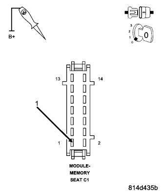
Disconnect the Memory Seat Module harness connector.
Disconnect the Adjustable Pedals Motor harness connector
Connect a jumper wire between the (P205) Adjustable Pedals Motor Forward circuit and ground in the Adjustable Pedal Motor harness connector.
Using a 12-volt test light connected to 12-volts, probe the (P205) Adjustable Pedals Motor Forward circuit in the Memory Seat Module harness connector.
Does the test light illuminate brightly?
Yes
- Go To 5
No
- Repair the Adjustable Pedals Motor Forward circuit for an open.
- Perform APS VERIFICATION TEST. (Refer to 5 - BRAKES/ELECTRICAL - STANDARD PROCEDURE).
5. CHECK (P206) ADJUSTABLE PEDALS MOTOR REARWARD CIRCUIT FOR AN OPEN
Connect a jumper wire between the Adjustable Pedals Motor Rearward circuit and ground in the Adjustable Pedal Motor harness connector.
Using a 12-volt test light connected to 12-volts, probe the (P206) Adjustable Pedals Motor Rearward circuit in the Memory Seat Module harness connector.
Does the test light illuminate brightly?
Yes
- Go To 6
No
- Repair the (P206) Adjustable Pedals Motor Rearward circuit for an open.
- Perform APS VERIFICATION TEST. (Refer to 5 - BRAKES/ELECTRICAL - STANDARD PROCEDURE).
6. CHECK (G912) SENSOR RETURN CIRCUIT FOR AN OPEN
Connect a jumper wire between the (G912) Sensor Return circuit and ground in the Adjustable Pedal Motor harness connector.
Using a 12-volt test light connected to 12-volts, probe the (G912) Sensor Return circuit.
Does the test light illuminate brightly?
Yes
- Go To 7
No
- Repair the (G912) Sensor Return circuit for an open.
- Perform APS VERIFICATION TEST. (Refer to 5 - BRAKES/ELECTRICAL - STANDARD PROCEDURE).
7. CHECK ADJUSTABLE PEDALS MOTOR
Measure the resistance between the (P205) Adjustable Pedals Motor Forward and (P206) Adjustable Pedals Motor Rearward terminals at the Adjustable Pedals Motor.
Is the resistance below 100.0 ohms?
Yes
- Replace and reprogram the Memory Seat Module in accordance with the Service Information.
- Perform APS VERIFICATION TEST. (Refer to 5 - BRAKES/ELECTRICAL - STANDARD PROCEDURE).
No
- Replace the Adjustable Pedals Motor in accordance with the Service Information.
- Perform APS VERIFICATION TEST. (Refer to 5 - BRAKES/ELECTRICAL - STANDARD PROCEDURE).
APS-INTERMITTENT CONDITION TEST
For a complete wiring diagram Refer to Section 8W.
Diagnostic Test
NOTE: The conditions that set the DTC are not present at this time. The following list may help in identifying the intermittent condition.
WARNING: When the engine is operating, do not stand in direct line with the fan. Do not put your hands near the pulleys, belts, or fan. Do not wear loose clothing. Failure to follow these instructions can result in personal injury or death.
Refer to any Technical Service Bulletins (TSBs) that may apply.
Review the scan tool information. If possible, try to duplicate the conditions under which the DTC set.
Turn the ignition off.
Visually inspect the related wire harness. Disconnect all the related harness connectors. Look for any chafed, pierced, pinched, partially broken wires and broken, bent, pushed out, or corroded terminals.
Wiggle the wires while checking for shorts and open circuits.
Perform a voltage drop test on the related circuits between the suspected faulty component and the Memory Seat Module.
Inspect and clean all grounds that are related to the most current DTC.
If numerous trouble codes were set, use a wiring schematic and look for any common ground or supply circuits
Monitor with the scan tool and wiggle the related wire harness to try to interrupt the actuation.
Use the scan tool to perform a System Test if one applies to failing component.
A co-pilot, data recorder, and/or lab scope should be used to help diagnose intermittent conditions.
Were any problems found during the above inspections?
Yes
- Perform the necessary repairs.
- Perform ABS VERIFICATION TEST. (Refer to 5 - BRAKES - STANDARD PROCEDURE).
No
- Test Complete.