P0875-UD HYDRAULIC PRESSURE TEST
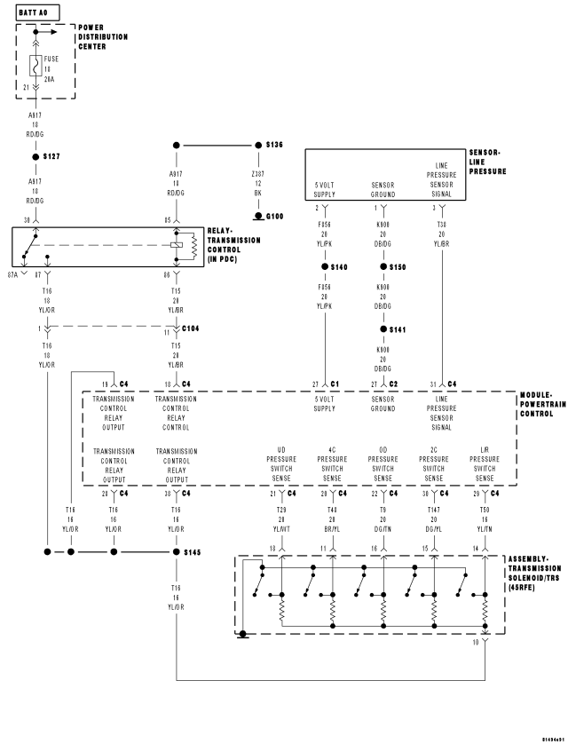
For a complete wiring diagram Refer to Section 8W
Theory of Operation
The Transmission Control System tests the pressure switches when they are off. The test verifies that the switches are operational (They will close with pressure applied). The Transmission Control System verifies that the switch closes when the corresponding element is applied. If a switch fails to close, it is re-tested. If it fails the second test, the DTC will set, the MIL will illuminate and the transmission system will default to the orderly Shutdown routine .
- When Monitored:
In any forward gear with engine speed above 1000 rpm shortly after a shift and every minute thereafter.
- Set Condition:
After a shift into a forward gear, with engine speed above 1000 rpm, the PCM momentarily turns on element pressure to the Clutch circuits that don't have pressure to identify the correct Pressure Switch closes. If the Pressure Switch does not close 2 times, the DTC sets.
| Possible Causes |
| LINE PRESSURE SENSOR |
| TRANSMISSION FLUID CONTAMINATION |
| RELATED DTC'S PRESENT |
| TRANSMISSION SOLENOID/TRS ASSEMBLY |
| EXCESSIVE DEBRIS IN OIL PAN |
| POOR LINE PRESSURE SENSOR CONNECTION |
| TRANSMISSION CONTROL RELAY DTCS PRESENT |
| (F856) 5-VOLT SUPPLY CIRCUIT OPEN |
| (F856) 5-VOLT SUPPLY CIRCUIT SHORT TO GROUND |
| (T29) UD PRESSURE SWITCH SENSE CIRCUIT SHORT TO ANOTHER CIRCUIT |
| TRANSMISSION SOLENOID/TRS ASSEMBLY |
| INTERNAL TRANSMISSION |
| POWERTRAIN CONTROL MODULE |
Always perform the 45RFE/545RFE Pre-Diagnostic Troubleshooting Procedure before proceeding. (Refer to 21 - TRANSMISSION/TRANSAXLE/AUTOMATIC - 45RFE/545RFE - STANDARD PROCEDURE)
Diagnostic Test
1. CHECK FOR RELATED DTCSWith the scan tool, check Transmission DTCs.
Is there any Loss of Prime, TCM Power Input, and/or Line Pressure Sensor DTCs present?
Yes
- Refer to the Transmission category and perform the appropriate symptom. If the DTC, P0944-LOSS OF PRIME is present, perform its respective test first.
No
- Go To 2
2. CHECK FOR DTC P0765
With the scan tool, check Transmission DTCs.
Is the DTC P0765 also present?
Yes
- Refer to the Transmission category and perform diagnostics for P0765-UD SOLENOID CIRCUIT.
No
- Go To 3
3. CHECK FOR OTHER DTCS
With the scan tool, check Transmission DTCs.
Are any of the DTCs, P0731, P0732, P0733, P0876, and/or P1736 present also?
Yes
- Go To 12
No
- Go To 4
4. CHECK IF DTC P0875 IS CURRENT
With the scan tool, check the STARTS SINCE SET counter for P0875.
Is the STARTS SINCE SET COUNTER 2 or less?
Yes
- Go To 5
No
- Go To 15
5. CHECK LINE PRESSURE
Start the engine.
Warm the transmission to 82° C (180° F).
Firmly apply the brakes.
With the scan tool, monitor the Line Pressure during the following step.
Move the shift lever to each gear position, pausing momentarily in each position and record the line pressure reading. Allow the pressure to stabilize for at least 5 seconds in each range.
Did the line pressure remain at a steady value between 585 and 655 kPa (85 and 95 psi) in each position?
Yes
- Go To 6
No
- Go To 10
6. CHECK LINE PRESSURE SENSOR CONNECTION
Ignition on, engine not running.
With the scan tool, monitor the Line Pressure while firmly pushing the Transmission Line Pressure Sensor connector inwards towards the Transmission.
Did the Line Pressure reading on the scan tool change to about 207 kPa (30 psi) when the connector was pushed inward?
Yes
- Disconnect and properly reconnect the Line Pressure Sensor connector. Inspect terminals and repair as necessary.
- Perform 45RFE/545RFE TRANSMISSION VERIFICATION TEST. (Refer to 21 - TRANSMISSION/TRANSAXLE/AUTOMATIC - 45RFE/545RFE - STANDARD PROCEDURE)
No
- Go To 7
7. CHECK LINE PRESSURE SENSOR OPERATION
Turn the ignition off to the lock position.
Remove the Starter Relay.
CAUTION: Removal of the Starter Relay will prevent the vehicle from being started in gear.
WARNING: The Starter Relay must be removed from the PDC. Failure to do so can result in personal injury or death.
NOTE: Failure to remove the Starter Relay can cause a Transmission - No Response condition.
Install the Transmission Simulator, Miller tool #8333.
With the Transmission Simulator select the "OFF" position on the "Input/Output Speed" switch.
Ignition on, engine not running.
With the scan tool, monitor the Line Pressure while turning the Pressure Switch selector to each of the 3 line pressure positions on the Transmission Simulator.
NOTE: All three scan tool Line Pressure readings should be steady and ±14 kPa (2.0 psi) of the reading specified on the Transmission Simulator.
Did the scan tool Line Pressure readings match the specified readings on the Transmission Simulator and remain steady in all three positions?
Yes
- Replace the Line Pressure Sensor per the Service Information.
- Perform 45RFE/545RFE TRANSMISSION VERIFICATION TEST. (Refer to 21 - TRANSMISSION/TRANSAXLE/AUTOMATIC - 45RFE/545RFE - STANDARD PROCEDURE)
No
- Go To 8
8. CHECK THE (F856) 5-VOLT SUPPLY CIRCUIT FOR AN OPEN
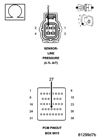
Turn the ignition off to the lock position.
Disconnect Transmission Simulator.
Disconnect the PCM C1 harness connector and connect Miller tool #8815.
CAUTION: Do not probe the PCM harness connectors. Probing the PCM harness connectors will damage the PCM terminals resulting in poor terminal to pin connection. Install Miller tool #8815 to perform diagnosis.
Measure the resistance of the (F856) 5-volt Supply circuit between the Line Pressure Sensor harness connector and the appropriate terminal of Miller tool #8815.
Is the resistance above 5.0 ohms?
Yes
- Repair the (F856) 5-volt Supply circuit for an open.
- Perform 45RFE/545RFE TRANSMISSION VERIFICATION TEST. (Refer to 21 - TRANSMISSION/TRANSAXLE/AUTOMATIC - 45RFE/545RFE - STANDARD PROCEDURE)
No
- Go To 9
9. CHECK THE (F856) 5-VOLT SUPPLY CIRCUIT FOR A SHORT TO GROUND
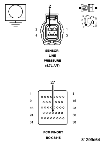
Measure the resistance between ground and the (F856) 5-volt Supply circuit.
Is the resistance below 5.0 ohms?
Yes
- Repair the (F856) 5-volt Supply circuit for a short to ground.
- Perform 45RFE/545RFE TRANSMISSION VERIFICATION TEST. (Refer to 21 - TRANSMISSION/TRANSAXLE/AUTOMATIC - 45RFE/545RFE - STANDARD PROCEDURE)
No
- Using the schematics as a guide, check the Powertrain Control Module (PCM) terminals for corrosion, damage, or terminal push out. Pay particular attention to all power and ground circuits. If no problems are found, replace and program the PCM per the Service Information. With the scan tool, perform QUICK LEARN.
- Perform 45RFE/545RFE TRANSMISSION VERIFICATION TEST. (Refer to 21 - TRANSMISSION/TRANSAXLE/AUTOMATIC - 45RFE/545RFE - STANDARD PROCEDURE)
10. COMPARE SCAN TOOL TO PRESSURE GAUGE
Turn the ignition off to the lock position.
Connect the Line Pressure Adapter, Miller tool #8259 and 0-300 psi Test Gauge, Miller tool #C-3293-SP. Refer to the Service Information for proper installation procedure.
CAUTION: Apply parking brake.
Start the engine.
In the following steps, compare the scan tool Line Pressure to the Pressure Gauge readings in each gear.
CAUTION: Do not overheat transmission.
With the gear selector in park, raise the rpm to 1500, and compare line pressure readings.
Firmly apply the brakes, move the gear selector into reverse, raise the rpm to 1500, and compare the line pressure readings.
Firmly apply the brakes, move the gear selector into drive, raise the rpm to 1500, and compare the line pressure readings.
Does the scan tool Line Pressure readings match the Pressure Gauge readings ± 10 psi?
Yes
- Go To 11
No
- Replace the Line Pressure Sensor per the Service Information.
- Perform 45RFE/545RFE TRANSMISSION VERIFICATION TEST. (Refer to 21 - TRANSMISSION/TRANSAXLE/AUTOMATIC - 45RFE/545RFE - STANDARD PROCEDURE)
11. CHECK WIRING AND CONNECTORS
Turn the ignition off to the lock position.
Remove the Line Pressure Adapter, Miller tool #8259 and 0-300 psi Test Gauge, Miller tool #C-3293-SP.
Remove the Starter Relay.
CAUTION: Removal of the Starter Relay will prevent the vehicle from being started in gear.
WARNING: The Starter Relay must be removed from the PDC. Failure to do so can result in personal injury or death.
NOTE: Failure to remove the Starter Relay can cause a Transmission - No Response condition.
Install the Transmission Simulator, Miller tool #8333.
On the Transmission Simulator, turn the Pressure Switch selector switch to UD.
Ignition on, engine not running.
With the scan tool, monitor the UD Pressure Switch state while pressing and holding the Pressure Switch test button and wiggling the wire harness and connectors that pertain to the UD Pressure Switch.
Did the UD Pressure Switch state change to closed and remain closed while wiggling the wires?
Yes
- Go To 12
No
- Go To 14
12. CHECK FOR EXCESSIVE DEBRIS
Turn the ignition off to the lock position.
Remove the Transmission Simulator, Miller tool #8333.
Remove and inspect the Transmission Oil Pan per the Service Information.
Does the Transmission Oil Pan contain excessive debris or contamination?
Yes
- Repair the cause of the excessive debris in the Transmission Oil Pan. Refer to the Service Information for the proper procedures.
- Perform 45RFE/545RFE TRANSMISSION VERIFICATION TEST. (Refer to 21 - TRANSMISSION/TRANSAXLE/AUTOMATIC - 45RFE/545RFE - STANDARD PROCEDURE)
No
- Go To 13
13. CHECK THE UD HYDRAULIC CLUTCH CIRCUIT
Remove the Valve Body and air check the UD hydraulic clutch circuit (in the case) for leakage per the Service Information.
NOTE: The UD hydraulic clutch circuit contains a small bleed orifice. A small amount of air leakage is normal.
Was there excessive air leakage noticed during the air check?
Yes
- Repair as necessary. Check the UD clutch piston, piston seals and bleed orifice, reaction shaft support seal rings, and machining of the main mating faces of the pump housing, pump valve body, and reaction shaft support.
- Perform 45RFE/545RFE TRANSMISSION VERIFICATION TEST. (Refer to 21 - TRANSMISSION/TRANSAXLE/AUTOMATIC - 45RFE/545RFE - STANDARD PROCEDURE)
No
- Disassemble and inspect the Valve Body and repair as necessary. Inspect the UD Accumulator piston and seals. If no problems are found in the Valve Body, replace the Transmission Solenoid/TRS Assembly per the Service Information.
- Perform 45RFE/545RFE TRANSMISSION VERIFICATION TEST. (Refer to 21 - TRANSMISSION/TRANSAXLE/AUTOMATIC - 45RFE/545RFE - STANDARD PROCEDURE)
14. CHECK THE (T29) UD PRESSURE SWITCH SENSE CIRCUIT FOR A SHORT TO ANOTHER CIRCUIT
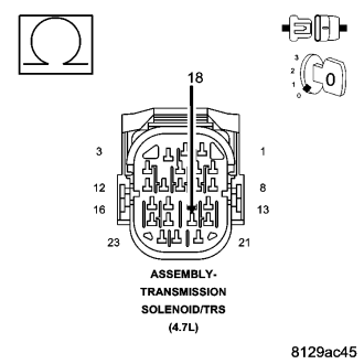
Disconnect all PCM harness connectors.
Disconnect the Transmission Solenoid/TRS Assembly harness connector.
NOTE: Make sure the Transmission Solenoid/TRS Assembly harness connector is disconnected.
NOTE: Check connectors - Clean/repair as necessary.
Measure the resistance between the (T29) UD Pressure Switch Sense circuit and all other circuits in the Transmission Solenoid/TRS Assembly harness connector.
Is the resistance below 5.0 ohms between the (T29) UD Pressure Switch Sense circuit and any other circuit(s) in the Transmission Solenoid/TRS Assembly harness connector?
Yes
- Repair the (T29) UD Pressure Switch Sense circuit for a short to another circuit(s).
- Perform 45RFE/545RFE TRANSMISSION VERIFICATION TEST. (Refer to 21 - TRANSMISSION/TRANSAXLE/AUTOMATIC - 45RFE/545RFE - STANDARD PROCEDURE)
No
- Using the schematics as a guide, check the Powertrain Control Module (PCM) terminals for corrosion, damage, or terminal push out. Pay particular attention to all power and ground circuits. If no problems are found, replace the PCM per the Service Information. With the scan tool, perform QUICK LEARN.
- Perform 45RFE/545RFE TRANSMISSION VERIFICATION TEST. (Refer to 21 - TRANSMISSION/TRANSAXLE/AUTOMATIC - 45RFE/545RFE - STANDARD PROCEDURE)
15. CHECK WIRING AND CONNECTORS
The conditions necessary to set this DTC are not present at this time.
Using the schematics as a guide, inspect the wiring and connectors specific to this circuit.
Wiggle the wires while checking for shorted and open circuits.
With the scan tool, check the DTC EVENT DATA to help identify the conditions in which the DTC was set.
If the DTC EVENT DATA shows the DTC P0875 set while the Line Pressure was significantly below the Desired Line Pressure reading, check for causes of low line pressure (low fluid level, broken or mis-installed primary oil filter or filter seal, sticking Main Regulator Valve in the Pump Valve Body etc.). If the data shows the DTC set while the Line Pressure reading was significantly higher than the Desired Line Pressure, check the Line Pressure Sensor and related wiring.
Where there any problems found?
Yes
- Repair as necessary.
- Perform 45RFE/545RFE TRANSMISSION VERIFICATION TEST. (Refer to 21 - TRANSMISSION/TRANSAXLE/AUTOMATIC - 45RFE/545RFE - STANDARD PROCEDURE)
No
- Test Complete.