P0890-SWITCHED BATTERY
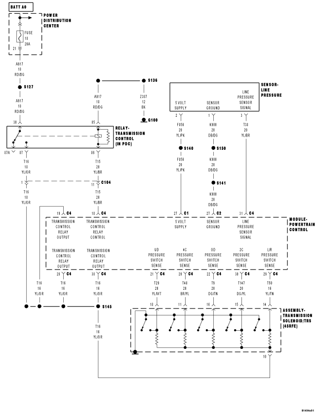
For a complete wiring diagram Refer to Section 8W.
Theory of Operation
The Transmission control relay is used to supply power to the solenoids and pressure switches (Transmission Solenoid/TRS Assembly) when the transmission is in normal operating mode. When the relay is off, no power is supplied and the transmission is in "limp-in" mode. The relay output is fed back to the PCM through pins C4-19, C4-28 and C4–38 and are referred to as "Transmission Control Relay Output".
Immediately after a controller reset (ignition key turned to the "run" position or after cranking engine), the TCM verifies that the relay contacts are open by checking for no voltage at the transmission control relay output terminals. After this is verified, the voltage at the pressure switches are checked. There should be no voltage on the pressure switches at this time. The PCM will then activate the relay.
- When Monitored:
When the ignition is turned from "OFF" position to "RUN" position and/or the ignition is turned from "START" position to "RUN" position.
- Set Condition:
This DTC is set if the Powertrain Control Module senses voltage on any of the pressure switch inputs prior to the Transmission Control Relay being energized.
| Possible Causes |
| PRESSURE SWITCH SENSE CIRCUITS SHORT TO VOLTAGE |
| TRANSMISSION SOLENOID/TRS ASSEMBLY |
| POWERTRAIN CONTROL MODULE |
Always perform the 45RFE/545RFE Pre-Diagnostic Troubleshooting Procedure before proceeding. (Refer to 21 - TRANSMISSION/TRANSAXLE/AUTOMATIC - 45RFE/545RFE - STANDARD PROCEDURE)
Diagnostic Test
1. CHECK TO SEE IF DTC P0890 IS PRESENTWith the scan tool, Check the STARTS SINCE SET counter for P0890.
NOTE: This counter only applies to the last DTC set.
Is the "Starts Since Set" counter set at 0?
Yes
- Go To 2
No
- Go To 4
2. PRESSURE SWITCH SENSE CIRCUITS SHORT TO VOLTAGE
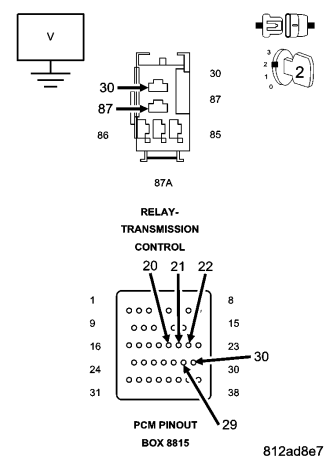
Turn the ignition off to the lock position.
Disconnect the PCM C4 harness connector and connect Miller tool #8815.
Disconnect the Transmission Solenoid/TRS Assembly harness connector.
Remove the Transmission Control Relay.
NOTE: Note: Check connectors - Clean/repair as necessary.
CAUTION: Do not probe the PCM harness connectors. Probing the PCM harness connectors will damage the PCM terminals resulting in poor terminal to pin connection. Install Miller tool #8815 to perform diagnosis.
Connect a jumper wire between the Fused B(+) circuit and the Transmission Control Relay Output circuit in the Transmission Control Relay connector.
Ignition on, engine not running.
Measure the voltage of the (T147) 2C, (T48) 4C, (T50) LR, (T9) OD, and (T29) UD Pressure Switch Sense circuits in Miller tool #8815.
Is the voltage above 0.5 volt on any of the measured circuits?
Yes
- Repair the (T147) 2C, (T48) 4C, (T50) LR, (T9) OD, and/or (T29) UD Pressure Switch Sense circuit(s) for a short to voltage.
- Perform 45RFE/545RFE TRANSMISSION VERIFICATION TEST. (Refer to 21 - TRANSMISSION/TRANSAXLE/AUTOMATIC - 45RFE/545RFE - STANDARD PROCEDURE)
No
- Go To 3
3. TRANSMISSION SOLENOID/TRS ASSEMBLY
Turn the ignition off.
Remove the jumper wire.
NOTE: Do not reinstall the Transmission Relay.
Reconnect the Transmission Solenoid/TRS Assembly harness connector.
Ignition on, engine not running.
Measure the voltage of the (T147) 2C, (T48) 4C, (T50) LR, (T9) OD, and (T29) UD Pressure Switch Sense circuits in Miller tool #8815.
Is the voltage above 0.5 volts on any of the sense circuits?
Yes
- Replace the Transmission Solenoid/TRS Assembly per the Service Information.
- Perform 45RFE/545RFE TRANSMISSION VERIFICATION TEST. (Refer to 21 - TRANSMISSION/TRANSAXLE/AUTOMATIC - 45RFE/545RFE - STANDARD PROCEDURE)
No
- Using the schematics as a guide, check the Powertrain Control Module (PCM) terminals for corrosion, damage, or terminal push out. Pay particular attention to all power and ground circuits. If no problems are found, replace the PCM per the Service Information. With the scan tool, perform QUICK LEARN.
- Perform 45RFE/545RFE TRANSMISSION VERIFICATION TEST. (Refer to 21 - TRANSMISSION/TRANSAXLE/AUTOMATIC - 45RFE/545RFE - STANDARD PROCEDURE)
4. INTERMITTENT WIRING AND CONNECTORS
The conditions necessary to set this DTC are not present at this time.
Using the schematics as a guide, inspect the wiring and connectors specific to this circuit.
Wiggle the wires while checking for shorted and open circuits.
With the scan tool, check the DTC EVENT DATA to help identify the conditions in which the DTC was set.
Where there any problems found?
Yes
- Repair as necessary.
- Perform 45RFE/545RFE TRANSMISSION VERIFICATION TEST. (Refer to 21 - TRANSMISSION/TRANSAXLE/AUTOMATIC - 45RFE/545RFE - STANDARD PROCEDURE)
No
- Test Complete.