P0958-AUTOSTICK CIRCUIT HIGH
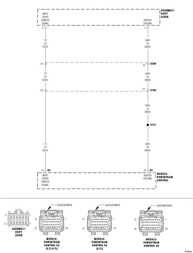
For a complete wiring diagram Refer to Section 8W
Theory of Operation
The AutoStick Switch is located in the Shift Lever Assembly (SLA). The gear requested by the AutoStick selection is then sent over the AutoStick Up/Down sense circuit to the PCM to engage the requested gear. Normal AutoStick® voltages are: Down = 0.71 to 1.11 volts, Up = 2.02 to 2.41 volts.
- When Monitored:
Ignition on and engine running and after 0.5 seconds.
- Set Condition:
When the monitored AutoStick Up/Down Sense circuit voltage rises above 4.75 volts.
| Possible Causes |
| (T5) AUTOSTICK UP/DOWN SENSE CIRCUIT OPEN |
| (K900) SENSOR GROUND CIRCUIT OPEN |
| (T5) AUTOSTICK UP/DOWN SENSE CIRCUIT SHORT TO VOLTAGE |
| (T5) AUTOSTICK UP/DOWN SENSE CIRCUIT SHORT TO ANOTHER CIRCUIT |
| SHIFT LEVER ASSEMBLY |
| TRANSMISSION CONTROL MODULE |
Always perform the 45RFE/545RFE Pre-Diagnostic Troubleshooting Procedure before proceeding. (Refer to 21 - TRANSMISSION/TRANSAXLE/AUTOMATIC - 45RFE/545RFE - STANDARD PROCEDURE)
Diagnostic Test
1. CHECK IF THE DTC IS CURRENTStart the engine in park.
With the scan tool, read the AutoStick® voltage.
Does the scan tool AutoStick voltage read above 4.75 volts?
Yes
- Go To 2
No
- Go To 7
2. CHECK THE (T5) AUTOSTICK UP/DOWN SENSE CIRCUIT FOR A OPEN
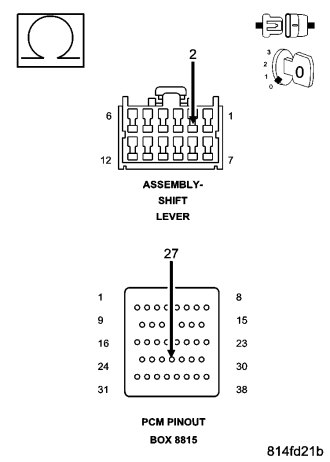
Turn the ignition off to the lock position.
Disconnect the PCM C3 harness connector and connect Miller tool #8815.
CAUTION: Do not probe the PCM harness connectors. Probing the PCM harness connectors will damage the PCM terminals resulting in poor terminal to pin connection. Install Miller tool #8815 to perform diagnosis.
Disconnect the Shift Lever Assembly harness connector.
Measure the resistance of the (T5) AutoStick Up/Down Sense circuit between the Shift Lever Assembly harness connector and the appropriate terminal of Miller tool #8815.
Is the resistance below 5.0 ohms?
Yes
- Go To 3
No
- Repair the (T5) AutoStick Up/Down Sense circuit for an open.
- Perform 45RFE/545RFE TRANSMISSION VERIFICATION TEST. (Refer to 21 - TRANSMISSION/TRANSAXLE/AUTOMATIC - 45RFE/545RFE - STANDARD PROCEDURE)
3. CHECK THE (K900) SENSOR GROUND CIRCUIT FOR AN OPEN
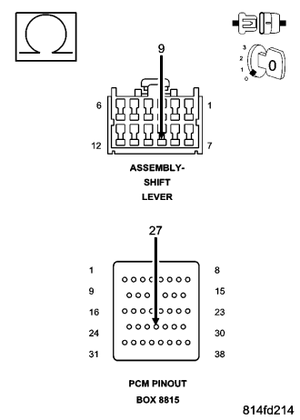
Disconnect the PCM C2 harness connector and connect Miller tool #8815.
Measure the resistance of the (K900) Sensor Ground circuit between the Shift Lever Assembly harness connector and the appropriate terminal of Miller tool #8815.
Is the resistance below 5.0 ohms?
Yes
- Go To 4
No
- Repair the (K900) Sensor Ground circuit for an open.
- Perform 45RFE/545RFE TRANSMISSION VERIFICATION TEST. (Refer to 21 - TRANSMISSION/TRANSAXLE/AUTOMATIC - 45RFE/545RFE - STANDARD PROCEDURE)
4. CHECK THE (T5) AUTOSTICK UP/DOWN SENSE CIRCUIT FOR A SHORT TO VOLTAGE
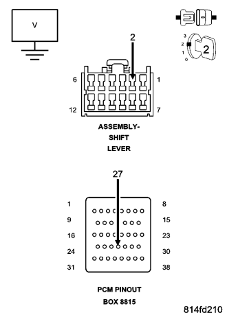
Ignition on, engine not running.
Measure the voltage of the (T5) AutoStick Up/Down Sense circuit.
Is the voltage above 0.5 volts?
Yes
- Repair the (T5) AutoStick Up/Down Sense circuit for a short to voltage.
- Perform 45RFE/545RFE TRANSMISSION VERIFICATION TEST. (Refer to 21 - TRANSMISSION/TRANSAXLE/AUTOMATIC - 45RFE/545RFE - STANDARD PROCEDURE)
No
- Go To 5
5. CHECK THE (T5) AUTOSTICK UP/DOWN SENSE CIRCUIT FOR A SHORT TO ANOTHER CIRCUIT
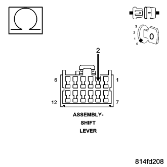
Turn the ignition off to the lock position.
Measure the resistance between the (T5) AutoStick Up/Down Sense circuit and all other circuits in the Shift Lever Assembly harness connector.
Is the resistance below 5.0 ohms between the (T5) AutoStick Up/Down Sense circuit and any other circuit(s) in the Shift Lever Assembly harness connector.
Yes
- Repair the (T5) AutoStick Up/Down Sense circuit for a short to another circuit(s).
- Perform 45RFE/545RFE TRANSMISSION VERIFICATION TEST. (Refer to 21 - TRANSMISSION/TRANSAXLE/AUTOMATIC - 45RFE/545RFE - STANDARD PROCEDURE)
No
- Go To6
6. CHECK THE AUTOSTICK SWITCH
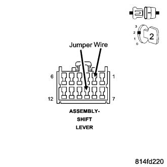
Reconnect the PCM C2 and C3 harness connectors.
Connect a jumper wire between (T5) AutoStick Up/Down Sense circuit and (K900) Sensor Ground circuit in the Shift Lever Assembly harness connector.
Ignition on, engine not running.
With the scan tool, read the AutoStick voltage.
Did the scan tool AutoStick voltage drop below 0.5 volts?
Yes
- Replace the Shift Lever Assembly per the Service Information.
- Perform 45RFE/545RFE TRANSMISSION VERIFICATION TEST. (Refer to 21 - TRANSMISSION/TRANSAXLE/AUTOMATIC - 45RFE/545RFE - STANDARD PROCEDURE)
No
- Using the schematics as a guide, check the Powertrain Control Module (PCM) terminals for corrosion, damage, or terminal push out. Pay particular attention to all power and ground circuits. If no problems are found, replace the PCM per the Service Information. With the scan tool, perform QUICK LEARN.
- Perform 45RFE/545RFE TRANSMISSION VERIFICATION TEST. (Refer to 21 - TRANSMISSION/TRANSAXLE/AUTOMATIC - 45RFE/545RFE - STANDARD PROCEDURE)
7. CHECK THE AUTOSTICK VOLTAGE WHILE SHIFTING
Start the engine in park.
With the brakes firmly applied, shift into AutoStick.
With the scan tool, monitor the AutoStick voltage while shifting both low and high.
Did the scan tool AutoStick voltage rise above 4.75 volts at any given time?
Yes
- Replace the Shift Lever Assembly per the Service Information.
- Perform 45RFE/545RFE TRANSMISSION VERIFICATION TEST. (Refer to 21 - TRANSMISSION/TRANSAXLE/AUTOMATIC - 45RFE/545RFE - STANDARD PROCEDURE)
No
- Go To 8
8. INTERMITTENT WIRING AND CONNECTORS
The conditions necessary to set this DTC are not present at this time.
Using the schematics as a guide, inspect the wiring and connectors specific to this circuit.
Wiggle the wiring and connectors while checking for any possible open or shorted circuits.
Check for any Service Information Tune-ups or Technical Service Bulletins that may apply.
Were there any problems found?
Yes
- Repair as necessary.
- Perform 45RFE/545RFE TRANSMISSION VERIFICATION TEST. (Refer to 21 - TRANSMISSION/TRANSAXLE/AUTOMATIC - 45RFE/545RFE - STANDARD PROCEDURE)
No
- Test Complete.