DIAGNOSIS AND TESTING
- AUTOMATIC TRANSMISSION
- PRELIMINARY
- ROAD TESTING
- HYDRAULIC PRESSURE TEST
- AIR CHECKING TRANSMISSION CLUTCH OPERATION
- CONVERTER HOUSING FLUID LEAK
AUTOMATIC TRANSMISSION
CAUTION: Before attempting any repair on a RFE automatic transmission, check for Diagnostic Trouble Codes with the scan tool.
Transmission malfunctions may be caused by these general conditions:
- Poor engine performance
- Improper adjustments
- Hydraulic malfunctions
- Mechanical malfunctions
- Electronic malfunctions
Diagnosis of these problems should always begin by checking the easily accessible variables: fluid level and condition, gearshift cable adjustment. Then perform a road test to determine if the problem has been corrected or if more diagnosis is necessary. If the problem persists after the preliminary tests and corrections are completed, hydraulic pressure checks should be performed.
PRELIMINARY
Two basic procedures are required. One procedure for vehicles that are drivable and an alternate procedure for disabled vehicles (will not back up or move forward).
VEHICLE IS DRIVABLE
1. Record all DTCs and the accompanying DTC Event Data.
2. Check for an appropriate Technical Service Bulletin that applies to the customer complaint.
3. Check fluid level and condition.
4. Road test and note how transmission upshifts, downshifts, and engages.
5. If the complaint was related to shift quality, perform the Quick Learn procedure, (Refer to 8 - ELECTRICAL/ELECTRONIC CONTROL MODULES/TRANSMISSION CONTROL MODULE - STANDARD PROCEDURE), and the Drive Learn Procedure, (Refer to 8 - ELECTRICAL/ELECTRONIC CONTROL MODULES/TRANSMISSION CONTROL MODULE - STANDARD PROCEDURE).
6. If the shift complaint still exists, compare actual line pressure (sensor reading, using the scan tool) to the Desired Line Pressure reading, in Park, Drive, and Reverse at 1500 RPM. Check that the LP sensor reads 30 psi (the minimum it should ever display) with key on / engine off.
7. Perform air-pressure test to check clutch operation. (Refer to 21 - TRANSMISSION/TRANSAXLE/AUTOMATIC - 45RFE/545RFE - DIAGNOSIS AND TESTING)
8. Replace the Transmission Solenoid/TRS Assembly and perform the Quick Learn and Drive Learn procedures again.
9. If the complaint still exists, remove, inspect, and repair the transmission as necessary
VEHICLE IS DISABLED
1. Record all DTCs and the accompanying DTC Event Data.
2. With engine running, place transmission in gear and verify correct PRNDL reading. Observe the Input and Output speeds using the scan tool. If output RPM is greater than zero but vehicle does not move, check for transfer case in Neutral (or failed internally), failed propshaft, or failed / disconnected drive axle. If output RPM is zero and input RPM is greater than zero, internal transmission slippage is indicated. Run clutch slip tests using the scan tool, check oil pan for debris, and air check the various clutch circuits.
3. Shift the transmission into neutral, if both input and output speeds are zero, check flexplate bolts, torque converter, and transmission input shaft.
4. Compare actual line pressure (sensor reading, using the scan tool) to the Desired Line Pressure reading, in Park, Drive, and Reverse at 1500 RPM. Check that the LP sensor reads 30 psi (the minimum it should ever display) with key on / engine off. If line pressure is incorrect, check fluid level and condition.
5. Remove, inspect, and repair the transmission as necessary
ROAD TESTING
Before road testing, be sure the fluid level and control cable adjustments have been checked and adjusted if necessary. Verify that all diagnostic trouble codes have been resolved.
Observe engine performance during the road test. A poorly tuned engine will not allow accurate analysis of transmission operation.
Operate the transmission in all gear ranges. Check for shift variations and engine flare which indicates slippage. Note if shifts are harsh, spongy, delayed, early, or if part throttle downshifts are sensitive.
Slippage indicated by engine flare, usually means clutch, overrunning clutch, or line pressure problems.
A slipping clutch can often be determined by comparing which internal units are applied in the various gear ranges. The Clutch Application charts provide a basis for analyzing road test results.
NOTE: Vehicles equipped with ERS will actually display as if the transmission were a six speed ( ERS second prime as third, third as fourth, fourth as fifth etc. .
| SLP |
UD |
OD |
R |
2C |
4C |
L/R |
OVERRUNNING |
| P–PARK |
ON |
||||||
| R–REVERSE |
ON |
ON |
|||||
| N-NEUTRAL |
ON |
||||||
| D–FIRST (ERS one) |
ON |
ON* |
ON |
||||
| D–SECOND (ERS two) |
ON |
ON |
|||||
| D–SECOND PRIME (ERS third) |
ON |
ON |
|||||
| D–THIRD (ERS fourth) |
ON |
ON |
|||||
| D–FOURTH (ERS fifth) |
ON |
ON |
|||||
| D–FIFTH (ERS drive) |
ON |
ON |
|||||
| D–LIMP-IN |
ON |
ON |
|||||
| 2–FIRST |
ON |
ON* |
ON |
||||
| 2–SECOND |
ON |
ON |
|||||
| 2–LIMP-IN |
ON |
ON |
|||||
| 1–LOW |
ON |
ON |
ON |
||||
| *L/R clutch is on only with the output shaft speed below 150 rpm. |
|||||||
HYDRAULIC PRESSURE TEST
An accurate tachometer and pressure test gauges are required. Oil Pressure Gauge C-3293-SP has a 300 psi range and is used at all locations where pressures exceed 100 psi.
Pressure Test Port Locations
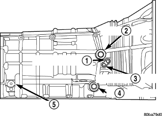
Only two pressure ports are supplied on the transmission case. The torque converter clutch apply (3) and release (1) ports are located on the right side of the transmission case.
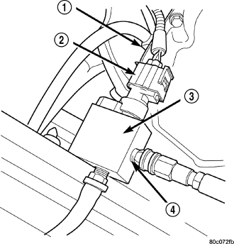
To determine the line pressure, there are two available methods. The scan tool can be used to read line pressure from the line pressure sensor. The second method is to install Line Pressure Adapter 8259 (3) into the transmission case and then install the pressure gauge and the original sensor (2) into the adapter. This will allow a comparison of the scan tool readings and the gauge reading to determine the accuracy of the line pressure sensor. The scan tool line pressure reading should match the gauge reading within ±10 psi.
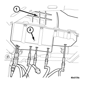
In order to access any other pressure tap locations, the transmission oil pan must be removed, the pressure port plugs removed and Valve Body Pressure Tap Adapter 8258-A (2) installed. The extensions supplied with Adapter 8258-A will allow the installation of pressure gauges to the valve body.
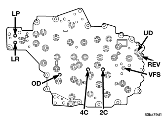
Refer to the Pressure Tap Locations graphic for correct pressure tap location identification.
TEST PROCEDURE
All pressure readings should be taken with the transmission fluid level full, transmission oil at the normal operating temperature, and the engine at 1500 rpm. Check the transmission for proper operation in each gear position that is in question or if a specific element is in question, check the pressure readings in at least two gear positions that employ that element. Refer to the Hydraulic Schematics at the rear of this section to determine the correct pressures for each element in a given gear position.
NOTE: The 545RFE utilizes closed loop control of pump line pressure. The pressure readings may therefore vary greatly but should always follow line pressure.
Some common pressures that can be measured to evaluate pump and clutch performance are the upshift/downshift pressures, garage shift pressures, and TCC pressure. The upshift/downshift pressure for all shifts are shown in UPSHIFT PRESSURES and DOWNSHIFT PRESSURES. In-gear maximum pressure for each gear position is shown in IN-GEAR PRESSURES. The garage shift pressure when performing a N-R shift is 220 psi for 4.7L equipped vehicles and 250 psi for 5.7L equipped vehicles. The garage shift pressure for the R-N shift is 120 psi. The garage shift pressure for the N-1 shift is 135 psi for 4.7L equipped vehicles and 165 psi for 5.7L equipped vehicles. Torque converter lock-up pressure is 120 psi for 4.7L equipped vehicles and 125 psi for 5.7L equipped vehicles.
| ENGINE |
1-2 |
2-3 |
2prime-3 |
3-4 |
2prime-4 |
2-5 |
3-5 |
4-5 |
| 5.7L |
150 |
125 |
125 |
135 |
135 |
135 |
135 |
135 |
| 4.7L |
120 |
120 |
120 |
120 |
120 |
120 |
120 |
130 |
| ENGINE |
5-4 |
5-3 |
5-2 |
4-3 |
4-2prime |
3-2 |
3-2prime |
2prime-1 |
2-1 |
3-1 |
| 5.7L |
135 |
135 |
135 |
135 |
135 |
135 |
135 |
135 |
135 |
135 |
| 4.7L |
120 |
120 |
120 |
120 |
120 |
120 |
120 |
120 |
120 |
120 |
| ENGINE |
1 |
2 |
2prime |
3 |
4 |
5 |
NEUTRAL |
REVERSE |
| 5.7L |
160 |
135 |
135 |
135 |
135 |
135 |
120 |
250 |
| 4.7L |
135 |
120 |
120 |
120 |
120 |
120 |
120 |
220 |
AIR CHECKING TRANSMISSION CLUTCH OPERATION
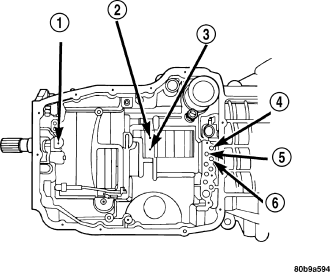
| 1 - LOW REVERSE CLUTCH |
| 2 - 4TH CLUTCH |
| 3 - 2ND CLUTCH |
| 4 - OVERDRIVE CLUTCH |
| 5 - UNDERDRIVE CLUTCH |
| 6 - REVERSE CLUTCH |
Air-pressure testing can be used to check transmission clutch operation. The test can be conducted with the transmission either in the vehicle or on the work bench, as a final check.
Air-pressure testing requires that the oil pan and valve body be removed from the transmission. The clutch apply passages are shown in the Air Pressure Test Passages graphic .
NOTE: The air supply which is used must be free of moisture and dirt. Use a pressure of 30 psi to test clutch operation.
Apply air pressure at each port. If the clutch is functioning, a soft thump will be heard as the clutch is applied. The clutch application can also be felt by touching the appropriate element while applying air pressure. As the air pressure is released, the clutch should also release.
CONVERTER HOUSING FLUID LEAK
When diagnosing converter housing fluid leaks, two items must be established before repair.
1. Verify that a leak condition actually exists.
2. Determined the true source of the leak.
Some suspected converter housing fluid leaks may not be leaks at all. They may only be the result of residual fluid in the converter housing, or excess fluid spilled during factory fill or fill after repair. Converter housing leaks have several potential sources. Through careful observation, a leak source can be identified before removing the transmission for repair. Torque converter seal leaks tend to move along the drive hub and onto the rear of the converter. Pump cover seal leaks tend to run down the cover and the inside surface of the bellhousing.
Some leaks, or suspected leaks, may be particularly difficult to locate. If necessary, a Mopar® approved dye should be used to locate and confirm a leak.
TORQUE CONVERTER LEAK POINTS
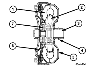
| 1 - TURBINE ASSEMBLY | 5 - IMPELLER ASSEMBLY |
| 2 - STATOR | 6 - CONVERTER CLUTCH PISTON |
| 3 - CONVERTER HUB | 7 - TURBINE HUB |
| 4 - O-RING |
Possible sources of converter leaks are:
1. Leaks at the weld joint around the outside diameter weld .
2. Leaks at the converter hub weld .
In most cases, a torque converter which is wet from transmission fluid indicates a leak at one of these areas.