PUMP-OIL
- DESCRIPTION
- OPERATION
- STANDARD PROCEDURE - OIL PUMP VOLUME CHECK
- DISASSEMBLY
- CLEANING
- INSPECTION
- ASSEMBLY
DESCRIPTION
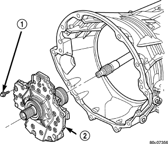
The oil pump (2) is located at the front of the transmission inside the bell housing and behind the transmission front cover.
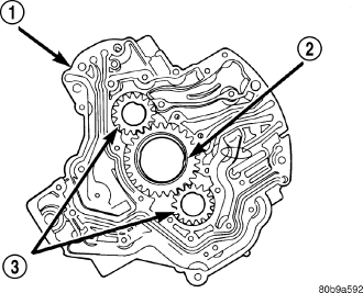
The oil pump consists of two independent pumps.
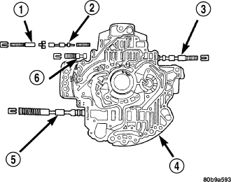
The oil pump also contains a number of valves. The converter clutch switch (3) and control valves (2), pressure regulator valve (5), and converter pressure limit valve (6) are all located in the oil pump valve body.
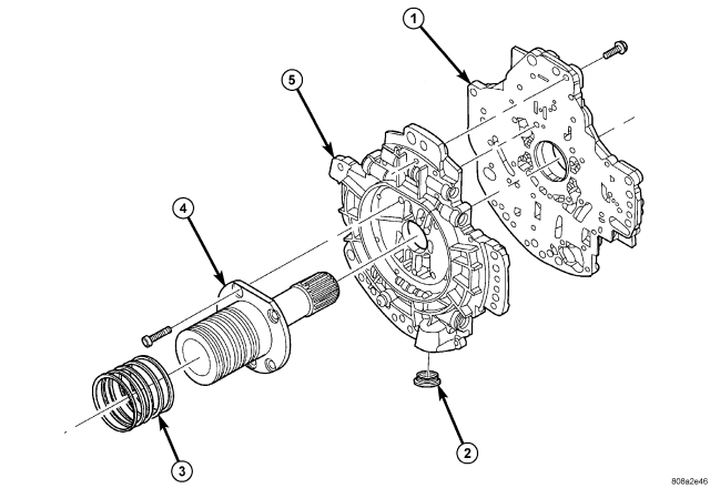
| Oil Pump Reaction Shaft |
| 1 - PUMP HOUSING |
4 - REACTION SHAFT SUPPORT |
| 2 - OIL FILTER SEAL |
5 - PUMP VALVE BODY |
| 3 - SEAL RING (5) |
A filter seal (2), and a bolt on reaction shaft (4) complete the oil pump assembly.
OPERATION
As the torque converter rotates, the converter hub rotates the oil pump drive gear. As the drive gear rotates both driven gears, a vacuum is created when the gear teeth come out of mesh. This suction draws fluid through the pump inlet from the oil pan. As the gear teeth come back into mesh, pressurized fluid is forced into the pump outlet and to the oil pump valves.
At low speeds, both sides of the pump supply fluid to the transmission. As the speed of the torque converter increases, the flow from both sides increases until the flow from the primary side alone is sufficient to meet system demands. At this point, the check valve located between the two pumps closes. The secondary side is shut down and the primary side supplies all the fluid to the transmission.
CONVERTER CLUTCH SWITCH VALVE
The converter clutch switch valve is used to control the direction of oil flow to the torque converter. When the converter clutch is released (CC switch valve downshifted), hydraulic pressure is supplied to the front (OFF) side of the torque converter clutch. When the converter clutch is applied (CC switch valve upshifted), regulated oil pressure is supplied to the back (ON) side of the converter clutch.
CONVERTER CLUTCH REGULATOR VALVE
The converter clutch regulator valve is used to control the hydraulic pressure supplied to the back (ON) side of the torque converter clutch.
TORQUE CONVERTER LIMIT VALVE
The torque converter limit valve serves to limit the available line pressure to the torque converter clutch.
STANDARD PROCEDURE - OIL PUMP VOLUME CHECK
Measuring the oil pump output volume will determine if sufficient oil flow to the transmission oil cooler exists, and whether or not an internal transmission failure is present.
Verify that the transmission fluid is at the proper level. Refer to the Fluid Level Check procedure in this section. If necessary, fill the transmission to the proper level with Mopar® ATF +4, Automatic Transmission Fluid.
1. Disconnect the To cooler line at the cooler inlet and place a collecting container under the disconnected line.
CAUTION: With the fluid set at the proper level, fluid collection should not exceed (1) quart or internal damage to the transmission may occur.
2. Run the engine at 1800 rpm, with the shift selector in neutral. Verify that the transmission fluid temperature is below 104.5° C (220° F) for this test.
3. If one quart of transmission fluid is collected in the container in 30 seconds or less, oil pump flow volume is within acceptable limits. If fluid flow is intermittent, or it takes more than 30 seconds to collect one quart of fluid, refer to the Hydraulic Pressure tests in this section for further diagnosis.
4. Re-connect the To cooler line to the transmission cooler inlet.
5. Refill the transmission to proper level.
DISASSEMBLY
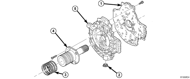
1. Remove the bolts holding the reaction shaft support (4) to the oil pump.
2. Remove the reaction shaft support (4) from the oil pump.
3. Remove all bolts holding the oil pump halves together.
4. Using suitable prying tools, separate the oil pump sections by inserting the tools in the supplied areas and prying the halves apart.
NOTE: The oil pump halves are aligned to each other through the use of two dowels. Be sure to pry upward evenly to prevent damage to the oil pump components.
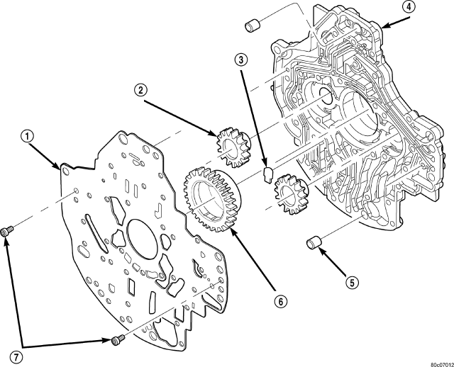
| Oil Pump Housing and Gears |
| 1 - SEPARATOR PLATE | 5 - DOWEL (2) |
| 2 - DRIVEN GEAR (2) | 6 - DRIVE GEAR |
| 3 - FLAPPER VALVE | 7 - SCREW |
| 4 - PUMP HOUSING |
5. Remove the screws (7) holding the separator plate (1) onto the oil pump housing (4).
6. Remove the separator plate (1) from the oil pump housing (4).
7. Mark all gears for location. The gears are select fit and if the oil pump is to be reused, the gears must be returned to their original locations.
8. Remove the oil pump flapper valve (3) from its pocket in the pump housing.
9. Remove the oil pump gears (2, 6) from the oil pump housing (4).
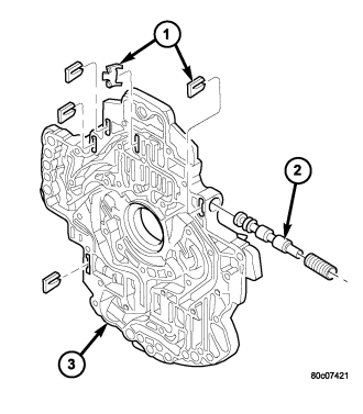
10. Remove the oil pump valve retainers (1) and associated valve (2) and spring one at a time. Mark the combination of components as a group and tag them as to the location from which they were removed.
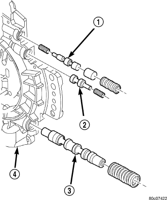
11. Remove the T/C regulator valve (1), T/C limit valve (2), and regulator valve (3).
CLEANING
Clean pump and support components with solvent and dry them with compressed air.
INSPECTION
Check condition of the seal rings and thrust washer on the reaction shaft support. The seal rings do not need to be replaced unless cracked, broken, or severely worn.
Inspect the pump and support components. Replace the pump or support if the seal ring grooves or machined surfaces are worn, scored, pitted, or damaged. Replace the pump gears if pitted, worn chipped, or damaged.
Inspect the pump reaction shaft support bushings. Replace either bushing only if heavily worn, scored or damaged. It is not necessary to replace the bushings unless they are actually damaged.
Inspect the valves and plugs for scratches, burrs, nicks, or scores. Minor surface scratches on steel valves and plugs can be removed with crocus cloth but do not round off the edges of the valve or plug lands. Maintaining sharpness of these edges is vitally important. The edges prevent foreign matter from lodging between the valves and plugs and the bore.
Inspect all the valve and plug bores in the oil pump valve body. Use a penlight to view the bore interiors. Replace the oil pump if any bores are distorted or scored. Inspect all of the valve springs. The springs must be free of distortion, warpage or broken coils.
Trial fit each valve and plug in its bore to check freedom of operation. When clean and dry, the valves and plugs should drop freely into the bores. Tip the pump valve body back and forth and check to see that each valve slides freely in its bore under its own weight (without pushing or prying).
ASSEMBLY
NOTE: Clean and inspect all components. Make sure that all passages are thoroughly cleaned and are free from dirt or debris. Make sure that all valves move freely in their proper bore. Make sure that all gear pockets and bushings are free from excessive wear and scoring. Replace the oil pump if any excessive wear or scoring is found.
1. Lubricate the oil pump valves with Mopar® ATF +4 and install the valve (2), spring, and retainer (1) into the appropriate oil pump valve body (3) bore.
2. Install the T/C regulator valve (1), T/C limit valve (2), and regulator valve (3).
NOTE: The pump separator plate is heat treated and therefore may exhibit a blue color or other discoloration in some areas. This is normal.
| Oil Pump Housing and Gears |
| 1 - SEPARATOR PLATE | 5 - DOWEL (2) |
| 2 - DRIVEN GEAR (2) | 6 - DRIVE GEAR |
| 3 - FLAPPER VALVE | 7 - SCREW |
| 4 - PUMP HOUSING |
3. Coat the gears (2, 6) with Mopar® ATF +4 and install into their original locations.
4. Place the oil pump flapper valve (3) into its pocket in the pump housing, with the rounded edges facing down.
5. Place the separator plate (1) onto the oil pump housing (4).
6. Install the screws (7) to hold the separator plate (1) onto the oil pump housing (4). Tighten the screws to 4.5 N·m (40 in.lbs.).
7. Position the oil pump valve body (5) onto the locating dowels.
8. Seat the two oil pump halves together and install all bolts finger tight.
9. Torque all bolts down slowly starting in the center and working outward. The correct torque is 4.5 N·m (40 in.lbs.).
10. Verify that the oil pump gears rotate freely and smoothly.
11. Position the reaction shaft support (4) onto the oil pump valve body (6).
12. Install and torque the bolts to hold the reaction shaft support (4) to the oil pump valve body (5). The correct torque is 12 N·m (105 in.lbs.).