K2-INPUT CLUTCH
DISASSEMBLY
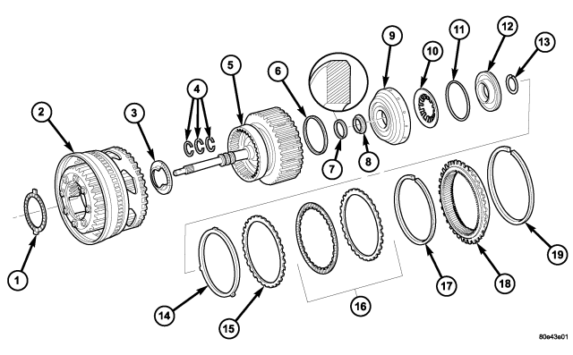
| Input Clutch K2 Components |
| 1 - NEEDLE ROLLER BEARING | 11 - SPRING RETAINER SEALING - O-RING |
| 2 - K1 INNER DISC CARRIER WITH INTEGRATED FRONT GEAR SET | 12 - SPRING RETAINER |
| 3 - THRUST BEARING | 13 - SNAP-RING |
| 4 - TORLON SEAL RINGS | 14 - DISC SPRING |
| 5 - INPUT SHAFT AND K2 CLUTCH | 15 - EXTERNALLY TOOTHED PLATE - 1.8 MM (0.071 IN.) |
| 6 - PISTON OUTER SEAL RING - O-RING | 16 - MULTIPLE DISC PACK |
| 7 - PISTON INNER SEAL RING | 17 - SNAP-RING |
| 8 - THRUST WASHER | 18 - HOLLOW GEAR |
| 9 - PISTON | 19 - SNAP-RING |
| 10 - DISC SPRING |
1. Remove snap-ring (19) from the K1 inner multiple-disc carrier with integrated front gear set (2) and take off hollow gear (18).
2. Remove input shaft with clutch K2 (5).
3. Remove needle thrust bearing (3).
4. Remove snap-ring (17) from K2 outer multiple-disc carrier.
5. Take out multiple-disc pack (16). Note which clutch disc is removed just prior to the disc spring (14) for re-assembly. If the clutch discs are re-used, this disc must be returned to its original position on top of the disc spring.
6. Take out disc spring (14).
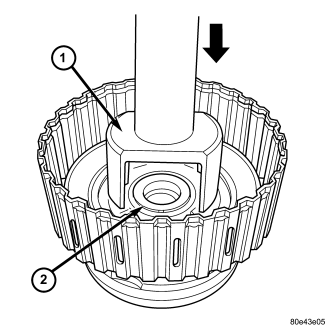
7. Fit Multi-use Spring Compressor 8900 (1) onto spring retainer (12) and press until snap-ring (2) is released.
8. Remove snap-ring (2) .
9. Take out disc spring (10) and pull piston (9) out of outer multiple-disc carrier.
ASSEMBLY
| Input Clutch K2 Components |
| 1 - NEEDLE ROLLER BEARING | 11 - SPRING RETAINER SEALING - O-RING |
| 2 - K1 INNER DISC CARRIER WITH INTEGRATED FRONT GEAR SET | 12 - SPRING RETAINER |
| 3 - THRUST BEARING | 13 - SNAP-RING |
| 4 - TORLON SEAL RINGS | 14 - DISC SPRING |
| 5 - INPUT SHAFT AND K2 CLUTCH | 15 - EXTERNALLY TOOTHED PLATE - 1.8 MM (0.071 IN.) |
| 6 - PISTON OUTER SEAL RING - O-RING | 16 - MULTIPLE DISC PACK |
| 7 - PISTON INNER SEAL RING | 17 - SNAP-RING |
| 8 - THRUST WASHER | 18 - HOLLOW GEAR |
| 9 - PISTON | 19 - SNAP-RING |
| 10 - DISC SPRING |
1. Install piston (9) in outer multiple-disc carrier. Inspect seals (6 and 7), replace if necessary. The rounded edges of the inner piston seal (7) must point to the outside.
2. Insert disk spring (10) and spring retainer (12). Insert disk spring (10) with curved side pointing toward spring retainer (12). Inspect seal (11), replace if necessary.
3. Place Multi-use Spring Compressor 8900 (1) on spring plate and press until the groove (2) of the snap-ring is exposed.
4. Insert snap-ring.
5. Insert disk spring (14).
NOTE: Pay attention to the sequence of discs. If the original clutch discs are reused, be sure to return the disc identified on disassembly as belonging on top of the disc spring (14) to its original location.
6. Insert multiple-disk set (16) into outer multiple-disk carrier.
7. Fit snap-ring (17).
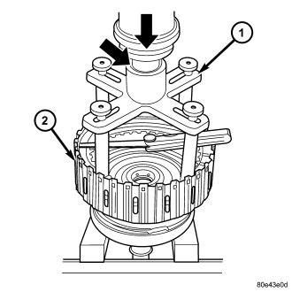
8. Measure K2 clutch clearance by mounting Pressing Tool 8901 (1) on outer multiple disc.
9. Using a lever press, compress pressing tool as far as the marking ring (the marking ring is still visible, see small arrow).
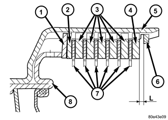
| 1 - DISC SPRING |
| 2 - OUTER MULTIPLE DISC - 1.8 MM (0.071 IN.) |
| 3 - OUTER MULTIPLE DISC - 3.5 MM (0.138 IN.) |
| 4 - OUTER MULTIPLE DISC - 4.0 MM (0.158 IN.) |
| 5 - K2 OUTER DISC CARRIER |
| 6 - SNAP-RING |
| 7 - FRICTION DISCS |
| 8 - PISTON |
10. Using a feeler gauge, determine the play "L" at three points between the snap-ring (6) and outer multiple-disc (4).
11. During the measurement the snap-ring (6) must contact the upper bearing surface of the groove in the outer multiple-disc carrier.
12. The correct clutch clearance is 2.3-2.7 mm (0.091-0.106 in.) for three friction disc versions, 2.4-2.8 mm (0.095-0.110 in.) for four disc versions, 2.5-2.9 mm (0.099-0.114 in.) for five disc versions, and 2.7-3.1 mm (0.106-0.122 in.) for six disc versions.
13. Adjust with snap-ring (6), if necessary. Snap-rings are available in thicknesses of 2.3 mm (0.091 in.), 2.6 mm (0.102 in.), 2.9 mm (0.114 in.), 3.2 mm (0.126 in.), 3.5 mm (0.138 in.), and 3.8 mm (0.150 in.).
| Input Clutch K2 Components |
| 1 - NEEDLE ROLLER BEARING | 11 - SPRING RETAINER SEALING - O-RING |
| 2 - K1 INNER DISC CARRIER WITH INTEGRATED FRONT GEAR SET | 12 - SPRING RETAINER |
| 3 - THRUST BEARING | 13 - SNAP-RING |
| 4 - TORLON SEAL RINGS | 14 - DISC SPRING |
| 5 - INPUT SHAFT AND K2 CLUTCH | 15 - EXTERNALLY TOOTHED PLATE - 1.8 MM (0.071 IN.) |
| 6 - PISTON OUTER SEAL RING - O-RING | 16 - MULTIPLE DISC PACK |
| 7 - PISTON INNER SEAL RING | 17 - SNAP-RING |
| 8 - THRUST WASHER | 18 - HOLLOW GEAR |
| 9 - PISTON | 19 - SNAP-RING |
| 10 - DISC SPRING |
14. Insert axial needle bearing (3) into K1 inner multiple-disk carrier. Insert axial needle bearing (3) with a little grease to prevent it slipping.
15. Install input shaft in K1 inner multiple-disc carrier with integrated front gear set (2).
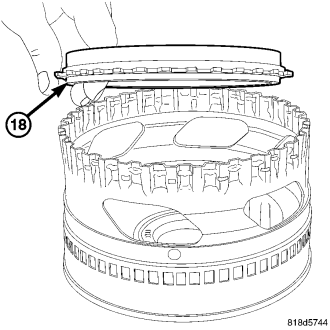
NOTE: Insure that the Hollow Gear (18) is oriented during installation such it protrudes from the K2 Retainer.
16. Fit internally-geared wheel (18) and install snap-ring.