POWER BRAKE BOOSTER
OPERATION
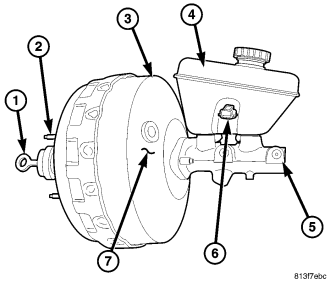
The atmospheric inlet valve is opened and closed by the primary push rod. Booster vacuum supply is through a hose attached to an intake manifold fitting at one end and to the booster check valve (7) at the other. The vacuum check valve in the booster housing is a one-way device that prevents vacuum leak back.
Power assist is generated by utilizing the pressure differential between normal atmospheric pressure and a vacuum. The vacuum needed for booster operation is taken directly from the engine intake manifold. The entry point for atmospheric pressure is through a filter and inlet valve at the rear of the housing.
The chamber areas forward of the booster diaphragms are exposed to vacuum from the intake manifold. The chamber areas to the rear of the diaphragms, are exposed to normal atmospheric pressure of 101.3 kilopascals (14.7 pounds/square in.).
Brake pedal application causes the primary push rod (1) to open the atmospheric inlet valve. This exposes the area behind the diaphragms to atmospheric pressure. The resulting pressure differential provides the extra apply force for power assist.
The booster check valve, check valve grommet (7) and booster seals are serviceable.REMOVAL
1. Siphon the master cylinder.
2. Remove the primary brake line at the master cylinder.
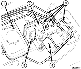
3. Remove the primary brake line from the HCU (4).
4. Remove the secondary brake line at the master cylinder.
5. Remove the secondary brake line at the HCU (4).
6. Remove the 4 chassis lines (3) at the HCU.
7. Disconnect the HCU electrical connector (5).
8. Remove the 3 mounting nuts at the HCU bracket (2).
9. Remove the HCU(1) with the bracket from the vehicle.
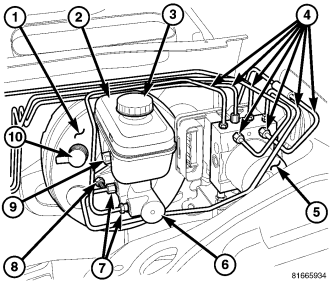
10. Disconnect the brake fluid level sensor electrical connector (9) from the fluid reservoir (2).
11. Remove the 2 master cylinder mounting nuts (8).
12. Remove the master cylinder (6).
13. Disconnect vacuum hose at booster check valve (10).
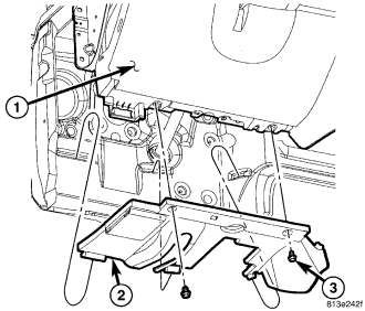
14. Remove the hush panel (2).
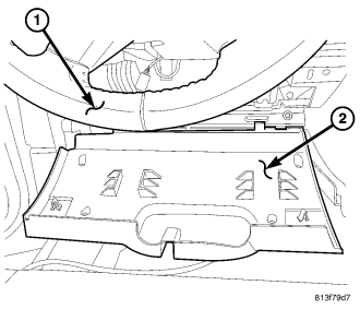
15. Remove the steering column opening cover (2) and hush panel.
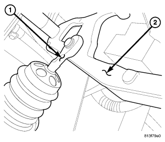
16. Remove retainer clip that holds booster push rod (1) on pedal pin (2). Then slide push rod off pin.
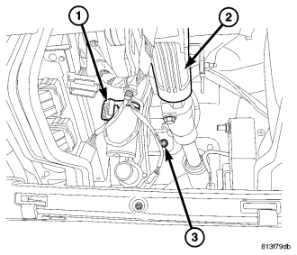
17. Disconnect the brake lamp switch wire connector.
18. Remove the brake lamp switch.
19. Remove four nuts (3) that attach booster to dash panel.
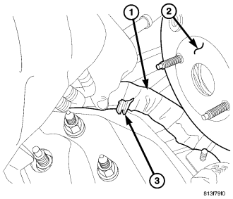
20. In the engine compartment, disconnect the wire harness routing clips (3) and move the harness (1) to the side and downward.
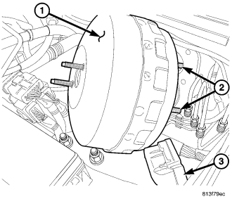
21. Remove the booster (1) from the vehicle.
INSTALLATION
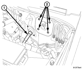
1. Check condition of grommet that secures check valve in booster. Replace grommet if cut, torn, or loose.
2. Install new booster dash seal.
3. Align and position booster in the mounting holes (2) of the dash panel.
4. Inside the vehicle, lubricate pedal pin with Mopar multi-mileage grease.
5. Install booster attaching nuts (3) on studs. Tighten attaching nuts to 39 N·m (29 ft. lbs.).
6. Slide booster push rod (1) on pedal pin. Then secure rod to pin with retainer clip.
7. Install a new brake lamp switch and reconnect the electrical connector.
8. Install the steering column opening cover (2).
9. Install the hush panel (2).
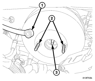
10. In engine compartment, attach vacuum hose to booster check valve (1).
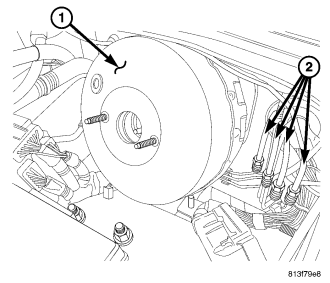
11. Install the master cylinder to the power brake booster (1) with new gasket and nuts.
12. Reroute the wire harness (1) back into position and install the routing clip (3).
13. Reconnect the brake fluid level electrical connector (9).
14. Install the HCU (1) with bracket (2) to the vehicle and tighten the 2 mounting nuts.
15. Reconnect the HCU electrical connector (5).
16. Install the 4 chassis lines (3) at the HCU (4).
17. Install the secondary brake line at the HCU (4).
18. Install the secondary brake line at the master cylinder.
19. Install the primary brake line at the HCU (4).
20. Install the primary brake linre at the master cylinder.
21. Fill and bleed brake system.