DISPLAY-PARK ASSIST
DESCRIPTION
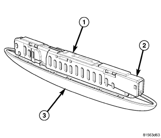
The rear park assist display (1) is located in the headliner at the rear of the vehicle, just forward of the upper liftgate opening header. The front park assist display is located in an escutcheon in the center of the instrument panel top pad near the windshield. Only the smoked clear plastic display lens (3) is visible on the headliner or the instrument panel. The lens prevents the 4 red Light Emitting Diode (LED) units and 12 amber LED units from being clearly visible unless they are illuminated by the electronic circuitry of the display.
The remainder of the display including the mounting provisions and the electrical connection are concealed above the headliner or below the instrument panel. A molded plastic housing with an integral connector receptacle (2) contains and protects the electronic circuitry of the display, including an audible tone transducer and an electronic communication chip.
The rear display has a stamped metal retainer with several tabs secured around the housing above the lens. The tabs of this retainer are folded over above the headliner substrate to secure the display in the opening in the headliner. The front display has six integral spring clips that snap through the opening in the molded plastic escutcheon on the instrument panel to secure it in place, while the escutcheon has several integral latch tabs that snap into the opening in the instrument panel top pad.
The park assist display is serviced only as a complete unit. It cannot be adjusted or repaired. If ineffective or damaged, the entire display unit must be replaced.
OPERATION
The park assist display provides the vehicle operator with visual feedback by illuminating amber or red Light Emitting Diode (LED) units individually or in unison, and audible feedback by energizing an audible tone transducer on the display electronic circuit board to emit either an intermittent or a continuous tone. While the park assist system is active, the number, position and color of the illuminated LED units as well as the audible signal frequency indicate the relative position and distance of obstacles detected at the front or rear of the vehicle.
The park assist display receives battery current and ground from and is completely controlled by the park assist module. The display also contains an electronic communication chip that allows bi-directional communication to occur with the park assist module over a dedicated serial bus line. The microprocessor in the park assist module completely controls the display outputs, continually monitors the display status, and will store a Diagnostic Trouble Code (DTC) in memory for any monitored fault it detects in the park assist display. The illumination intensity of the LED units is also controlled by the park assist module based upon internal programming and panel lamps dimming electronic messages received over the Controller Area Network (CAN) data bus.
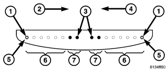
When the ignition switch is turned to the ON position, all 16 of the LED units in the display will illuminate in unison for approximately 1 second as a bulb test. This output will be interrupted if the system is active and senses an obstacle. Following the conclusion of the bulb test, when the system is active but no obstacle is detected, the display will indicate system readiness by illuminating the two outermost amber LED units (1) at a reduced intensity. As an obstacle is detected, the outermost amber LED unit (5) on the side of the vehicle where the obstacle was detected will be illuminated at normal intensity. Then additional amber LED units (6) will begin illuminating inward (2 or 4) as the obstacle gets closer until, finally, the two red LED units (7) are illuminated.
When the final red LED unit (3) is illuminated, the obstacle is approximately 40 centimeters (16 inches) from the front or rear bumper and an intermittent audible tone will be generated. The frequency of the audible tone will increase as the obstacle continues to become closer until the tone is continuous when the obstacle is about 30 centimeters (12 inches) from the front or rear bumper. Whenever a park assist audible tone is being generated, the park assist module sends electronic messages to the radio over the Controller Area Network (CAN) data bus to mute the audio system. The audible tone will be cancelled after about two seconds if the detected distance to the obstacle remains constant. See the Park Assist Display Outputs table for additional details.
The hard wired circuits between components related to the park assist display may be diagnosed using conventional diagnostic tools and procedures. Refer to the appropriate wiring information. The wiring information includes wiring diagrams, proper wire and connector repair procedures, details of wire harness routing and retention, connector pin-out information and location views for the various wire harness connectors, splices and grounds.
However, conventional diagnostic methods will not prove conclusive in the diagnosis of the park assist display or the electronic controls or communication between modules and other devices that provide some features of the park assist system. The most reliable, efficient, and accurate means to diagnose the park assist display or the electronic controls and communication related to park assist display operation requires the use of a diagnostic scan tool. Refer to the appropriate diagnostic information.
| PARK ASSIST DISPLAY OUTPUTS |
|||||||||
| DISPLAY LED |
DETECTION DISTANCE |
LED COLOR |
AUDIBLE SIGNAL |
||||||
| FRONT CORNERS |
FRONT CENTER |
REAR CORNERS |
REAR CENTER |
||||||
| 1st LED |
150 cm (59 in.) |
150 cm (59 in.) |
Amber |
None |
|||||
| 2nd LED |
120 cm (47 in.) |
120 cm (47 in.) |
Amber |
None |
|||||
| 3rd LED |
100 cm (39 in.) |
100 cm (39 in.) |
Amber |
None |
|||||
| 4th LED |
80 cm (31.5 in.) |
80 cm (31.5 in.) |
80 cm (31.5 in.) |
80 cm (31.5 in.) |
Amber |
None |
|||
| 5th LED |
65 cm (25.5 in.) |
65 cm (25.5 in.) |
65 cm (25.5 in.) |
65 cm (25.5 in.) |
Amber |
None |
|||
| 6th LED |
50 cm (20 in.) |
50 cm (20 in.) |
50 cm (20 in.) |
50 cm (20 in.) |
Amber |
None |
|||
| 7th LED |
40 cm (16 in.) |
40 cm (16 in.) |
40 cm (16 in.) |
40 cm (16 in.) |
Red |
40 cm (16 in.) Intermittent |
|||
| 8th LED |
15 cm (6 in.) |
30 cm (12 in.) |
15 cm (6 in.) |
30 cm (12 in.) |
Red |
30 cm (12 in.) Continuous |
|||