SWITCH-PARK ASSIST
DESCRIPTION
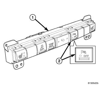
The park assist switch (2) is integral to the lower switch pod (1) in the instrument panel center stack below the heater and air conditioner controls. This switch is a normally open, momentary contact type unit that is actuated by depressing the appropriate rectangular molded black plastic push button on the face of the switch pod. The park assist switch push button is clearly identified with a white International Control and Display Symbol graphic for Parking Aid and the text OFF. An amber Light Emitting Diode (LED) unit is illuminated behind a small clear plastic jewel-like lens in the push button to give a visual indication whenever the park assist system has been manually disabled with the ignition switch in the ON or START positions.
The park assist switch cannot be adjusted or repaired and, is serviced only as a unit with the lower instrument panel switch pod. If the switch is ineffective or damaged, the entire switch pod must be replaced as a unit. (Refer to 8 - ELECTRICAL/INSTRUMENT CLUSTER/INSTRUMENT PANEL SWITCH POD - DESCRIPTION - LOWER).
OPERATION
The park assist switch is connected in series between ground and an input terminal of the ElectroMechanical Instrument Cluster (EMIC) (also known as the Cab Compartment Node/CCN). Each time the switch is depressed it provides a momentary ground signal to the EMIC, which the EMIC reads through an internal pull-up. The EMIC responds by sending an electronic park assist switch pressed message to the park assist module over the Controller Area Network (CAN) data bus.
The park assist module responds to each park assist switch pressed message by toggling the status of the park assist system from enabled to disabled, or from disabled to enabled, then sends an electronic park assist system status message back to the EMIC over the CAN bus. The EMIC responds to this status message by toggling a transistor that controls a voltage output to the grounded park assist switch Light Emitting Diode (LED) unit so that the LED is illuminated with the system disabled and the ignition switch in the ON or START positions, and is extinguished with the system enabled or with the ignition switch in any position except ON or START.
The hard wired circuits between components related to the park assist switch may be diagnosed using conventional diagnostic tools and procedures. Refer to the appropriate wiring information. The wiring information includes wiring diagrams, proper wire and connector repair procedures, details of wire harness routing and retention, connector pin-out information and location views for the various wire harness connectors, splices and grounds.
However, conventional diagnostic methods will not prove conclusive in the diagnosis of the electronic controls or communication between modules and other devices that provide some features of the park assist system. The most reliable, efficient, and accurate means to diagnose the park assist switch or the electronic controls and communication related to park assist switch operation requires the use of a diagnostic scan tool. Refer to the appropriate diagnostic information.