RELAY-BLOWER MOTOR
DESCRIPTION
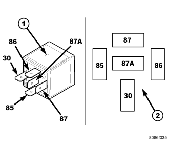
The blower motor relay (1) for the heating-A/C system is an International Standards Organization (ISO)-type relay. Relays conforming to the ISO specifications have common physical dimensions, current capacities, terminal functions and patterns (2). The blower motor relay is a electromechanical device that switches battery current through a fuse in the power distribution center (PDC) directly to the blower motor when equipped with the manual temperature control (MTC) system, or to the blower motor power module when equipped with the automatic temperature control (ATC) system. The blower motor relay is energized when the relay coil is provided battery current by the ignition switch.
The blower motor relay is located in the PDC in the engine compartment.
OPERATION
The ISO-standard blower motor relay is an electromechanical switch that uses a low current input from the ignition switch to control the high current output to the blower motor. The movable, common feed relay contact is held against the fixed, normally closed relay contact by spring pressure. When the electromagnetic relay coil is energized, it draws the movable common feed relay contact away from the fixed, normally closed relay contact and, holds it against the fixed, normally open relay contact. This action allows high current to flow to the blower motor.
When the relay coil is de-energized, spring pressure returns the movable relay contact back against the fixed, normally closed contact point. The resistor or diode is connected in parallel with the relay coil, and helps to dissipate voltage spikes and electromagnetic interference that can be generated as the electromagnetic field of the relay coil collapses.
The blower motor relay terminals are connected to the vehicle electrical system through a receptacle in the power distribution center (PDC). The inputs and outputs of the blower motor relay include:
- Terminal (30) receives fused battery current at all times.
- Terminal (85) is connected to a ground circuit at all times.
- Terminal (86) receives fused battery current through the run relay only when the run relay coil is energized.
- Terminal (87) provides fused battery current to the blower motor through the blower motor relay only when the blower motor relay coil is energized.
- Terminal (87A) is not connected to any circuit in this application, but provides a battery current output only when the blower motor relay coil is de-energized.
The blower motor relay cannot be repaired and must be replaced if found inoperative or damaged. Refer to the appropriate wiring information for diagnosis and testing of the ISO-standard relay and for complete HVAC wiring diagrams.
REMOVAL
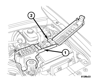
NOTE: LHD gasoline model shown. Diesel and RHD models similar.
1. Disconnect and isolate the negative battery cable.
2. Open the cover of the power distribution center (PDC) (1) located in the engine compartment.
NOTE: Refer to the fuse and relay layout map on the inside of the PDC cover for blower motor relay location.
3. Remove the blower motor relay (2) from the PDC.
INSTALLATION
NOTE: LHD gasoline model shown. Diesel and RHD models similar.
1. Position the blower motor relay (2) into the proper receptacle of the power distribution center (PDC) (1).
NOTE: Refer to the fuse and relay layout map on the inside of the PDC cover for blower motor relay location.
2. Align the blower motor relay terminals with the terminal cavities in the PDC receptacle and push down firmly on the relay until the terminals are fully seated.
3. Close the cover of the PDC.
4. Reconnect the negative battery cable.