DIAGNOSIS AND TESTING
- FDCM VERIFICATION TEST
- C1417-FRONT DIFFERENTIAL CONTROL CIRCUIT LOW
- C1418-FRONT DIFFERENTIAL CONTROL CIRCUIT HIGH
- C141A-FRONT DIFFERENTIAL CONTROL CIRCUIT “CURRENT” PERFORMANCE
- C141B-FRONT DIFFERENTIAL CLUTCH PERFORMANCE
- C141D-REAR DIFFERENTIAL CONTROL CIRCUIT LOW
- C141E-REAR DIFFERENTIAL CONTROL CIRCUIT HIGH
- C1420-REAR DIFFERENTIAL CONTROL CIRCUIT “CURRENT” PERFORMANCE
- C1421-REAR DIFFERENTIAL CLUTCH PERFORMANCE
- C2109-DRIVETRAIN SUPPLY VOLTAGE CIRCUIT LOW
FDCM VERIFICATION TEST
Diagnostic Test
1. PERFORM FDCM VERIFICATION TESTNOTE: If the SKIM, PCM or FCM was replaced, refer to the service information for proper programming procedures.
- Disconnect all jumper wires and reconnect all previously disconnected components and connectors.
- Ensure that all accessories are turned off.
- Ensure that the battery is fully charged.
- If the FDCM was replaced as part of the repair you must program the new FDCM using the scan tool.
- With the scan tool, record and erase all DTC(s) from the FDCM
- Start and run the engine for 2 minutes while operating all functions of the system that caused the original concern.
- Turn the ignition off, wait 5 seconds, then turn the ignition on. Using the scan tool, read DTC(s) from the FDCM.
Are any FDCM DTC(s) present or is the original condition still present?
Yes
- The repair is not complete. Refer to the related category for the DTC or symptom that is still present.
No
- The repair is complete.
C1417-FRONT DIFFERENTIAL CONTROL CIRCUIT LOW
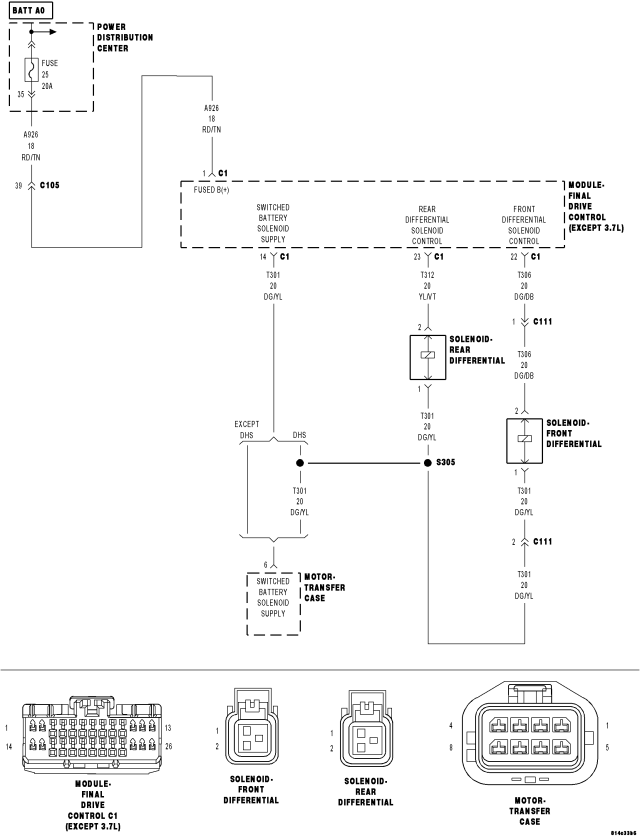
For a complete wiring diagram Refer to Section 8W.
- When Monitored:
The Solenoid is active, no solenoid supply circuit DTCs are present and battery voltage is normal.
- Set Condition:
The FDCM detects the Front Differential Solenoid Control is shorted low.
| Possible Causes |
| FRONT DIFFERENTIAL SOLENOID |
| (T306) FRONT DIFFERENTIAL SOLENOID CONTROL CIRCUIT SHORTED TO GROUND |
| (T306) FRONT DIFFERENTIAL SOLENOID CONTROL CIRCUIT OPEN |
| (T301) SWITCHED BATTERY SOLENIOD SUPPLY OPEN/SHORTED TO GROUND |
| FINAL DRIVE CONTROL MODULE (FDCM) |
Diagnostic Test
1. ACTIVE DTCIgnition on, engine not running.
With the scan tool, read DTCs.
Is the DTC active at this time?
Yes
- Go To 2
No
- Go To8
2. FRONT DIFFERENTIAL SOLENOID OPERATION
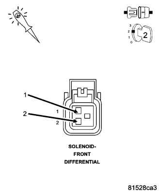
Turn the ignition off.
Disconnect the Front Differential Solenoid harness connector.
Ignition on, engine not running.
Using a 12-volt test light, jump across from the (T301) Switch Battery Solenoid Supply circuit and the (T306) Front Differential Solenoid Control circuit in the Front Differential Solenoid harness connector.
With the scan tool, clear DTCs in the FDCM.
With the scan tool, actuate the Front Differential Solenoid.
Does the test light illuminate brightly and flash on and off?
Yes
- Inspect the Front Differential Solenoid Jumper harness, repair/replace as necessary. If OK, replace the Front Differential Solenoid.
- Perform FDCM VERIFICATION TEST.
No
- Go To 3
3. (T306) FRONT DIFFERENTIAL SOLENOID CONTROL CIRCUIT SHORTED TO GROUND
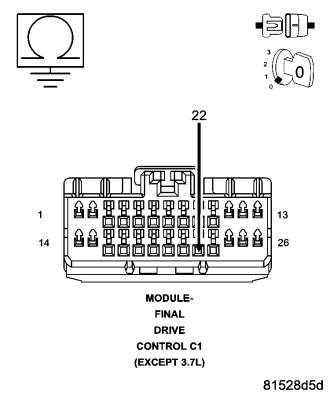
Turn the ignition off.
Disconnect the FDCM harness connector.
Measure the resistance of the (T306) Front Differential Solenoid Control circuit at the FDCM harness connector to ground.
Is the resistance below 100 ohms?
Yes
- Repair the short to ground in the Front Differential Solenoid Control circuit.
- Perform FDCM VERIFICATION TEST.
No
- Go To 4
4. (T306) FRONT DIFFERENTIAL SOLENOID CONTROL CIRCUIT OPEN
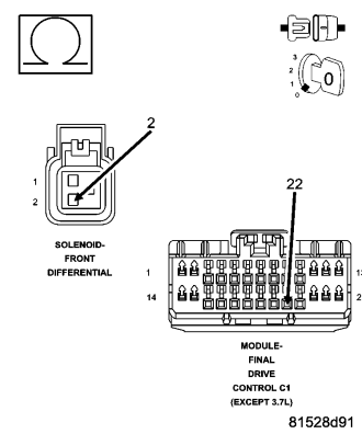
Measure the resistance of the (T306) Front Differential Solenoid Control circuit between the Front Differential Solenoid harness connector and the FDCM harness connector.
Is the resistance below 5.0 ohms?
Yes
- Go To 5
No
- Repair the open in the (T306) Front Differential Solenoid Control circuit.
- Perform FDCM VERIFICATION TEST
5. (T301) SWITCHED BATTERY SOLENOID SUPPLY CIRCUIT SHORTED TO GROUND
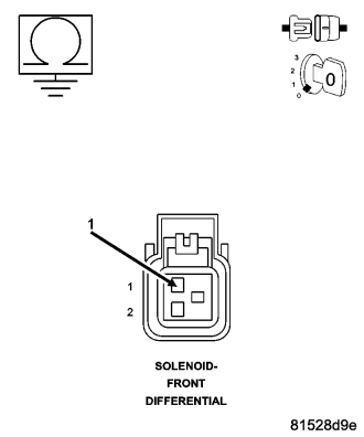
Measure the resistance of the (T301) Switched Battery Solenoid Supply circuit at the Front Solenoid Differential harness connector to ground.
Is the resistance below 100 ohms?
Yes
- Repair the short to ground in the (T301) Switched Battery Solenoid Supply circuit.
- Perform FDCM VERIFICATION TEST.
No
- Go To 6
6. (T301) SWITCHED BATTERY SOLENOID SUPPLY CIRCUIT OPEN
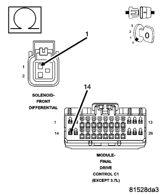
Measure the resistance of the (T301) Switched Battery Solenoid Supply circuit between the Front Differential Solenoid harness connector and the FDCM harness connector.
Is the resistance below 5.0 ohms?
Yes
- Go To 7
No
- Repair the open in the (T301) Switched Battery Solenoid Supply circuit.
- Perform FDCM VERIFICATION TEST
- Go To 7
7. FDCM
NOTE: Before continuing, check the FDCM harness connector terminals for corrosion, damage, or terminal push out. Repair as necessary.
Using the schematics as a guide, inspect the wire harness and connectors. Pay particular attention to all Power and Ground circuits.
Were there any problems found?
Yes
- Repair as necessary.
- Perform FDCM VERIFICATION TEST
No
- Replace and program the Final Drive Control Module in accordance with Service Information.
- Perform FDCM VERIFICATION TEST.
8. INTERMITTENT WIRING AND CONNECTORS
The conditions necessary to set this DTC are not present at this time.
Using the schematics as a guide, inspect the wiring and connectors specific to this circuit.
Wiggle test the wiring harness and connectors while checking for shorted and open circuits.
Using the scan tool, monitor the data related to this circuit while performing the wiggle test. Look for the data to change or for the DTC to reset.
Were there any problems found?
Yes
- Repair as necessary.
- Perform FDCM VERIFICATION TEST.
No
- Test Complete.
C1418-FRONT DIFFERENTIAL CONTROL CIRCUIT HIGH
For a complete wiring diagram Refer to Section 8W.
- When Monitored:
The Solenoid is active, no solenoid supply circuit DTCs are present and battery voltage is normal.
- Set Condition:
The FDCM detects the Front Differential Solenoid Control is high.
| Possible Causes |
| FRONT DIFFERENTIAL SOLENOID |
| (T306) FRONT DIFFERENTIAL SOLENOID CONTROL CIRCUIT SHORTED TO BATTERY VOLTAGE |
| (T306) FRONT DIFFERENTIAL SOLENOID CONTROL CIRCUIT SHORTED TO (T301) SWITCHED BATTERY SOLENOID SUPPLY CIRCUIT |
| FINAL DRIVE CONTROL MODULE (FDCM) |
Diagnostic Test
1. ACTIVE DTCIgnition on, engine not running.
With the scan tool, read DTCs.
Is the DTC active at this time?
Yes
- Go To 2
No
- Go To6
2. FRONT DIFFERENTIAL SOLENOID OPERATION
Turn the ignition off.
Disconnect the Front Differential Solenoid harness connector.
Ignition on, engine not running.
Using a 12-volt test light, jump across from the (T306) Front Differential Solenoid Control circuit and the (T301) Switched Battery Solenoid Supply circuit in the Front Differential Solenoid harness connector.
With the scan tool, clear DTCs in the FDCM.
With a scan tool, actuate the Front Differential Solenoid.
Does the test light flash on and off?
Yes
- Inspect the Front Differential Solenoid Jumper harness connector, repair/replace as necessary. If OK, replace the Front Differential Solenoid.
- Perform FDCM VERIFICATION TEST.
No
- Go To 3
3. (T306) FRONT DIFFERENTIAL SOLENOID CONTROL CIRCUIT SHORTED TO BATTERY VOLTAGE
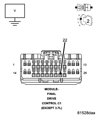
Turn the ignition off.
Disconnect the FDCM harness connector.
Turn the ignition on.
Measure the voltage on the (T306) Front Differential Solenoid Control circuit at the FDCM harness connector.
Does the voltmeter indicate voltage present?
Yes
- Repair the short to voltage in the (T306) Front Differential Solenoid Control circuit.
- Perform FDCM VERIFICATION TEST.
No
- Go To 4
4. (T306) FRONT DIFFERENTIAL SOLENOID CONTROL CIRCUIT SHORTED TO (T301) SWITCHED BATTERY SOLENOID SUPPLY CIRCUIT
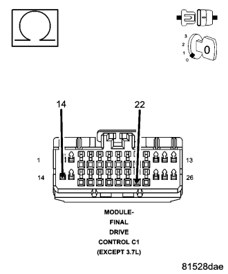
Measure the resistance between the (T306) Front Differential Solenoid Control circuit and the (T301) Switched Battery Solenoid Supply circuit in the FDCM harness connector.
Is the resistance below 100 ohms?
Yes
- Repair the short between the (T306) Front Differential Solenoid Control circuit and the (T301) Switched Battery Solenoid Supply circuit.
- Perform FDCM VERIFICATION TEST
No
- Go To 5
5. FDCM
NOTE: Before continuing, check the FDCM harness connector terminals for corrosion, damage, or terminal push out. Repair as necessary.
Using the schematics as a guide, inspect the wire harness and connectors. Pay particular attention to all Power and Ground circuits.
Were there any problems found?
Yes
- Repair as necessary.
- Perform FDCM VERIFICATION TEST
No
- Replace and program the Final Drive Control Module in accordance with Service Information.
- Perform FDCM VERIFICATION TEST.
6. INTERMITTENT WIRING AND CONNECTORS
The conditions necessary to set this DTC are not present at this time.
Using the schematics as a guide, inspect the wiring and connectors specific to this circuit.
Wiggle test the wiring harness and connectors while checking for shorted and open circuits.
Using the scan tool, monitor the data related to this circuit while performing the wiggle test. Look for the data to change or for the DTC to reset.
Were there any problems found?
Yes
- Repair as necessary.
- Perform FDCM VERIFICATION TEST.
No
- Test Complete.
C141A-FRONT DIFFERENTIAL CONTROL CIRCUIT “CURRENT” PERFORMANCE
For a complete wiring diagram Refer to Section 8W.
- When Monitored:
The ignition on. No Solenoid DTCs present.
- Set Condition:
The FDCM detects a current feedback when the solenoid is not active.
| Possible Causes |
| WIRING HARNESS INSPECTION |
| FDCM |
Diagnostic Test
1. ACTIVE DTCNOTE: You must diagnose any Solenoid circuit (Low or High) DTCs first if set along with this DTC before continuing.
Ignition on, engine not running.
With the scan tool, read DTCs.
Is the DTC active at this time?
Yes
- Go To 2
No
- Go To3
2. WIRING HARNESS INSPECTION
Inspect the wiring harness from both solenoids to the FDCM. Ensure that the harness has routed correctly.
Inspect the FDCM harness connector and Differential Solenoid connectors. Ensure the terminals are clean and no damage is present.
Was the wiring harness and connectors OK?
Yes
- Replace the FDCM in accordance with the Service Manual.
- Perform FDCM VERIFICATION TEST.
No
- Repair as necessary.
- Perform FDCM VERIFICATION TEST.
3. INTERMITTENT WIRING AND CONNECTORS
The conditions necessary to set this DTC are not present at this time.
Using the schematics as a guide, inspect the wiring and connectors specific to this circuit.
Wiggle test the wiring harness and connectors while checking for shorted and open circuits.
Using the scan tool, monitor the data related to this circuit while performing the wiggle test. Look for the data to change or for the DTC to reset.
Were there any problems found?
Yes
- Repair as necessary.
- Perform FDCM VERIFICATION TEST.
No
- Test Complete.
C141B-FRONT DIFFERENTIAL CLUTCH PERFORMANCE
For a complete wiring diagram Refer to Section 8W.
- When Monitored:
The ignition on. No Solenoid DTCs present.
- Set Condition:
The solenoid duty cycle is greater than 95% and the wheel slippage is greater than 50%.
| Possible Causes |
| WIRING HARNESS INSPECTION |
| DIFFERENTIAL (MECHANICAL) |
| FRONT DIFFERENTANTIAL SOLENOID |
Diagnostic Test
1. ACTIVE DTCNOTE: You must diagnose any Solenoid circuit (Low or High) DTCs first if set along with this DTC before continuing.
Ignition on, engine not running.
With the scan tool, read DTCs.
Is the DTC active at this time?
Yes
- Go To 2
No
- Go To4
2. WIRING HARNESS INSPECTION
Inspect the wiring harness from both solenoids to the FDCM. Ensure that the harness has routed correctly.
Inspect the FDCM harness connector and Differential Solenoid connectors. Ensure the terminals are clean and no damage is present.
Was the wiring harness and connectors OK?
Yes
- Go To 3
No
- Repair as necessary.
- Perform FDCM VERIFICATION TEST.
3. INSPECTION DIFFERENTIAL
Ensure the Differential is operating properly. Refer to 3–Differential & Driveline Service Information.
Inspect the Differential for external fluid leaks. Repair as necessary, refer to 3–Differential & Driveline Service Information.
Is the Differential operating properly?
Yes
- Replace the Front Differential Solenoid.
- Perform FDCM VERIFICATION TEST.
No
- Repair as necessary.
- Perform FDCM VERIFICATION TEST.
4. INTERMITTENT WIRING AND CONNECTORS
The conditions necessary to set this DTC are not present at this time.
Using the schematics as a guide, inspect the wiring and connectors specific to this circuit.
Wiggle test the wiring harness and connectors while checking for shorted and open circuits.
Using the scan tool, monitor the data related to this circuit while performing the wiggle test. Look for the data to change or for the DTC to reset.
Were there any problems found?
Yes
- Repair as necessary.
- Perform FDCM VERIFICATION TEST.
No
- Test Complete.
C141D-REAR DIFFERENTIAL CONTROL CIRCUIT LOW
For a complete wiring diagram Refer to Section 8W.
- When Monitored:
The Solenoid is active, no solenoid supply circuit DTCs are present and battery voltage is normal.
- Set Condition:
The FDCM detects the Rear Differential Solenoid Control is shorted low.
| Possible Causes |
| REAR DIFFERENTIAL SOLENOID |
| (T312) REAR DIFFERENTIAL SOLENOID CONTROL CIRCUIT SHORTED TO GROUND |
| (T312) REAR DIFFERENTIAL SOLENOID CONTROL CIRCUIT OPEN |
| (T301) SWITCHED BATTERY SOLENIOD SUPPLY OPEN/SHORTED TO GROUND |
| FINAL DRIVE CONTROL MODULE (FDCM) |
Diagnostic Test
1. ACTIVE DTCIgnition on, engine not running.
With the scan tool, read DTCs.
Is the DTC active at this time?
Yes
- Go To 2
No
- Go To8
2. REAR DIFFERENTIAL SOLENOID OPERATION
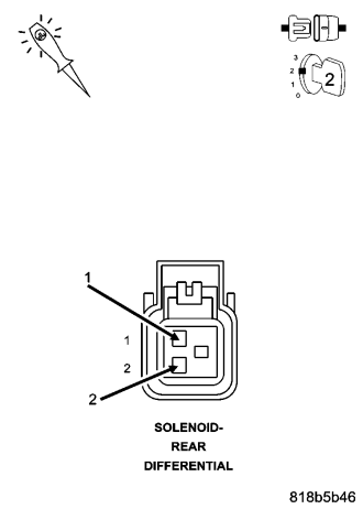
Turn the ignition off.
Disconnect the Rear Differential Solenoid harness connector.
Ignition on, engine not running.
Using a 12-volt test light, jump across from the (T301) Switch Battery Solenoid Supply circuit and the (T312) Rear Differential Solenoid Control circuit in the Rear Differential Solenoid harness connector.
With the scan tool, clear DTCs in the FDCM.
With the scan tool, actuate the Rear Differential Solenoid.
Does the test light illuminate brightly and flash on and off?
Yes
- Inspect the Rear Differential Solenoid Jumper harness, repair/replace as necessary. If OK, replace the Rear Differential Solenoid.
- Perform FDCM VERIFICATION TEST.
No
- Go To 3
3. (T312) REAR DIFFERENTIAL SOLENOID CONTROL CIRCUIT SHORTED TO GROUND
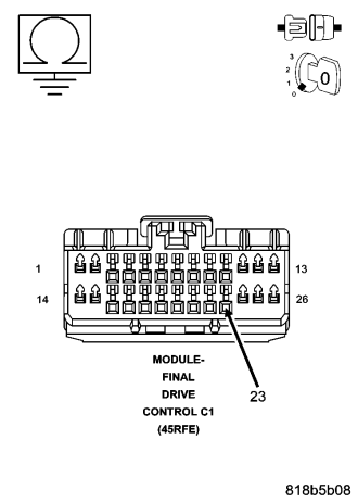
Turn the ignition off.
Disconnect the FDCM harness connector.
Measure the resistance of the (T312) Rear Differential Solenoid Control circuit at the FDCM harness connector to ground.
Is the resistance below 100 ohms?
Yes
- Repair the short to ground in the Rear Differential Solenoid Control circuit.
- Perform FDCM VERIFICATION TEST.
No
- Go To 4
4. (T312) REAR DIFFERENTIAL SOLENOID CONTROL CIRCUIT OPEN
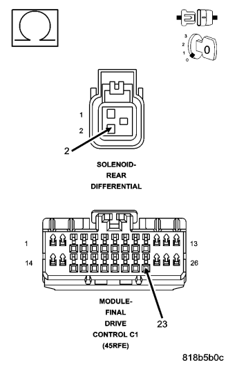
Measure the resistance of the (T312) Rear Differential Solenoid Control circuit between the Rear Differential Solenoid harness connector and the FDCM harness connector.
Is the resistance below 5.0 ohms?
Yes
- Go To 5
No
- Repair the open in the (T312) Rear Differential Solenoid Control circuit.
- Perform FDCM VERIFICATION TEST
5. (T301) SWITCHED BATTERY SOLENOID SUPPLY CIRCUIT SHORTED TO GROUND
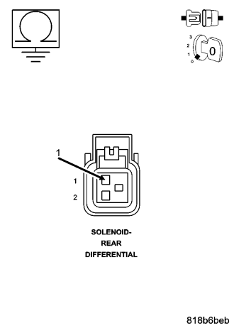
Measure the resistance of the (T301) Switched Battery Solenoid Supply circuit at the Rear Solenoid Differential harness connector to ground.
Is the resistance below 100 ohms?
Yes
- Repair the short to ground in the (T301) Switched Battery Solenoid Supply circuit.
- Perform FDCM VERIFICATION TEST.
No
- Go To 6
6. (T301) SWITCHED BATTERY SOLENOID SUPPLY CIRCUIT OPEN
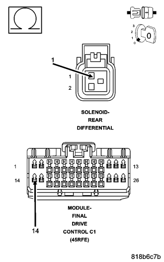
Measure the resistance of the (T301) Switched Battery Solenoid Supply circuit between the Rear Differential Solenoid harness connector and the FDCM harness connector.
Is the resistance below 5.0 ohms?
Yes
- Go To 7
No
- Repair the open in the (T301) Switched Battery Solenoid Supply circuit.
- Perform FDCM VERIFICATION TEST
- Go To 7
7. FDCM
NOTE: Before continuing, check the FDCM harness connector terminals for corrosion, damage, or terminal push out. Repair as necessary.
Using the schematics as a guide, inspect the wire harness and connectors. Pay particular attention to all Power and Ground circuits.
Were there any problems found?
Yes
- Repair as necessary.
- Perform FDCM VERIFICATION TEST
No
- Replace and program the Final Drive Control Module in accordance with Service Information.
- Perform FDCM VERIFICATION TEST.
8. INTERMITTENT WIRING AND CONNECTORS
The conditions necessary to set this DTC are not present at this time.
Using the schematics as a guide, inspect the wiring and connectors specific to this circuit.
Wiggle test the wiring harness and connectors while checking for shorted and open circuits.
Using the scan tool, monitor the data related to this circuit while performing the wiggle test. Look for the data to change or for the DTC to reset.
Were there any problems found?
Yes
- Repair as necessary.
- Perform FDCM VERIFICATION TEST.
No
- Test Complete.
C141E-REAR DIFFERENTIAL CONTROL CIRCUIT HIGH
For a complete wiring diagram Refer to Section 8W.
- When Monitored:
The Solenoid is active, no solenoid supply circuit DTCs are present and battery voltage is normal.
- Set Condition:
The FDCM detects the Rear Differential Solenoid Control is high.
| Possible Causes |
| REAR DIFFERENTIAL SOLENOID |
| (T312) REAR DIFFERENTIAL SOLENOID CONTROL CIRCUIT SHORTED TO BATTERY VOLTAGE |
| (T312) REAR DIFFERENTIAL SOLENOID CONTROL CIRCUIT SHORTED TO (T301) SWITCHED BATTERY SOLENOID SUPPLY CIRCUIT |
| FINAL DRIVE CONTROL MODULE (FDCM) |
Diagnostic Test
1. ACTIVE DTCIgnition on, engine not running.
With the scan tool, read DTCs.
Is the DTC active at this time?
Yes
- Go To 2
No
- Go To6
2. REAR DIFFERENTIAL SOLENOID OPERATION
Turn the ignition off.
Disconnect the Rear Differential Solenoid harness connector.
Ignition on, engine not running.
Using a 12-volt test light, jump across from the (T312) Rear Differential Solenoid Control circuit and the (T301) Switched Battery Solenoid Supply circuit in the Rear Differential Solenoid harness connector.
With the scan tool, clear DTCs in the FDCM.
With a scan tool, actuate the Rear Differential Solenoid.
Does the test light flash on and off?
Yes
- Inspect the Rear Differential Solenoid Jumper harness connector, repair/replace as necessary. If OK, replace the Rear Differential Solenoid.
- Perform FDCM VERIFICATION TEST.
No
- Go To 3
3. (T312) REAR DIFFERENTIAL SOLENOID CONTROL CIRCUIT SHORTED TO BATTERY VOLTAGE
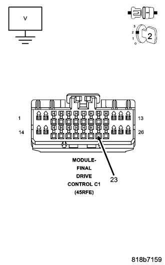
Turn the ignition off.
Disconnect the FDCM harness connector.
Turn the ignition on.
Measure the voltage on the (T312) Rear Differential Solenoid Control circuit at the FDCM harness connector.
Does the voltmeter indicate voltage present?
Yes
- Repair the short to voltage in the (T312) Rear Differential Solenoid Control circuit.
- Perform FDCM VERIFICATION TEST.
No
- Go To 4
4. (T312) REAR DIFFERENTIAL SOLENOID CONTROL CIRCUIT SHORTED TO (T301) SWITCHED BATTERY SOLENOID SUPPLY CIRCUIT
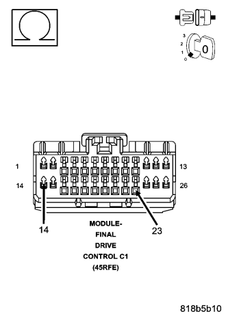
Measure the resistance between the (T312) Rear Differential Solenoid Control circuit and the (T301) Switched Battery Solenoid Supply circuit in the FDCM harness connector.
Is the resistance below 100 ohms?
Yes
- Repair the short between the (T312) Rear Differential Solenoid Control circuit and the (T301) Switched Battery Solenoid Supply circuit.
- Perform FDCM VERIFICATION TEST
No
- Go To 5
5. FDCM
NOTE: Before continuing, check the FDCM harness connector terminals for corrosion, damage, or terminal push out. Repair as necessary.
Using the schematics as a guide, inspect the wire harness and connectors. Pay particular attention to all Power and Ground circuits.
Were there any problems found?
Yes
- Repair as necessary.
- Perform FDCM VERIFICATION TEST
No
- Replace and program the Final Drive Control Module in accordance with Service Information.
- Perform FDCM VERIFICATION TEST.
6. INTERMITTENT WIRING AND CONNECTORS
The conditions necessary to set this DTC are not present at this time.
Using the schematics as a guide, inspect the wiring and connectors specific to this circuit.
Wiggle test the wiring harness and connectors while checking for shorted and open circuits.
Using the scan tool, monitor the data related to this circuit while performing the wiggle test. Look for the data to change or for the DTC to reset.
Were there any problems found?
Yes
- Repair as necessary.
- Perform FDCM VERIFICATION TEST.
No
- Test Complete.
C1420-REAR DIFFERENTIAL CONTROL CIRCUIT “CURRENT” PERFORMANCE
For a complete wiring diagram Refer to Section 8W.
- When Monitored:
The ignition on. No Solenoid DTCs present.
- Set Condition:
The FDCM detects a current feedback when the solenoid is not active.
| Possible Causes |
| WIRING HARNESS INSPECTION |
| FDCM |
Diagnostic Test
1. ACTIVE DTCNOTE: You must diagnose any Solenoid circuit (Low or High) DTCs first if set along with this DTC before continuing.
Ignition on, engine not running.
With the scan tool, read DTCs.
Is the DTC active at this time?
Yes
- Go To 2
No
- Go To3
2. WIRING HARNESS INSPECTION
Inspect the wiring harness from both solenoids to the FDCM. Ensure that the harness has routed correctly.
Inspect the FDCM harness connector and Differential Solenoid connectors. Ensure the terminals are clean and no damage is present.
Was the wiring harness and connectors OK?
Yes
- Replace the FDCM in accordance with the Service Manual.
- Perform FDCM VERIFICATION TEST.
No
- Repair as necessary.
- Perform FDCM VERIFICATION TEST.
3. INTERMITTENT WIRING AND CONNECTORS
The conditions necessary to set this DTC are not present at this time.
Using the schematics as a guide, inspect the wiring and connectors specific to this circuit.
Wiggle test the wiring harness and connectors while checking for shorted and open circuits.
Using the scan tool, monitor the data related to this circuit while performing the wiggle test. Look for the data to change or for the DTC to reset.
Were there any problems found?
Yes
- Repair as necessary.
- Perform FDCM VERIFICATION TEST.
No
- Test Complete.
C1421-REAR DIFFERENTIAL CLUTCH PERFORMANCE
For a complete wiring diagram Refer to Section 8W.
- When Monitored:
The ignition on. No Solenoid DTCs present.
- Set Condition:
The solenoid duty cycle is greater than 95% and the wheel slippage is greater than 50%.
| Possible Causes |
| WIRING HARNESS INSPECTION |
| DIFFERENTIAL (MECHANICAL) |
| REAR DIFFERENTANTIAL SOLENOID |
Diagnostic Test
1. ACTIVE DTCNOTE: You must diagnose any Solenoid circuit (Low or High) DTCs first if set along with this DTC before continuing.
Ignition on, engine not running.
With the scan tool, read DTCs.
Is the DTC active at this time?
Yes
- Go To 2
No
- Go To4
2. WIRING HARNESS INSPECTION
Inspect the wiring harness from both solenoids to the FDCM. Ensure that the harness has routed correctly.
Inspect the FDCM harness connector and Differential Solenoid connectors. Ensure the terminals are clean and no damage is present.
Was the wiring harness and connectors OK?
Yes
- Go To 3
No
- Repair as necessary.
- Perform FDCM VERIFICATION TEST.
3. INSPECTION DIFFERENTIAL
Ensure the Differential is operating properly. Refer to 3–Differential & Driveline Service Information.
Inspect the Differential for external fluid leaks. Repair as necessary, refer to 3–Differential & Driveline Service Information.
Is the Differential operating properly?
Yes
- Replace the Rear Differential Solenoid.
- Perform FDCM VERIFICATION TEST.
No
- Repair as necessary.
- Perform FDCM VERIFICATION TEST.
4. INTERMITTENT WIRING AND CONNECTORS
The conditions necessary to set this DTC are not present at this time.
Using the schematics as a guide, inspect the wiring and connectors specific to this circuit.
Wiggle test the wiring harness and connectors while checking for shorted and open circuits.
Using the scan tool, monitor the data related to this circuit while performing the wiggle test. Look for the data to change or for the DTC to reset.
Were there any problems found?
Yes
- Repair as necessary.
- Perform FDCM VERIFICATION TEST.
No
- Test Complete.
C2109-DRIVETRAIN SUPPLY VOLTAGE CIRCUIT LOW
For a complete wiring diagram Refer to Section 8W.
- When Monitored:
Ignition on.
- Set Condition:
The FDCM recognizes the Switched Battery Solenoid Supply circuit voltage is too low.
| Possible Causes |
| (T301) SWITCHED BATTERY SOLENOID SUPPLY CIRCUIT OPEN |
| (T301) SWITCHED BATTERY SOLENOID SUPPLY CIRCUIT SHORTED TO GROUND |
| FRONT DIFFERENTIAL SOLENOID |
| REAR DIFFERENTIAL SOLENOID |
| TRANSFER CASE MOTOR |
| FINAL DRIVE CONTROL MODULE (FDCM) |
Diagnostic Test
1. ACTIVE DTCIgnition on, engine not running.
With a scan tool, read DTCs.
Is the DTC active at this time?
Yes
- Go To 2
No
- Go To 8
2. (T301) SWITCHED BATTERY SOLENOID SUPPLY CIRCUIT OPEN
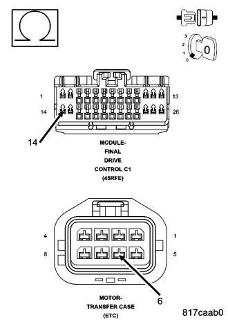
Turn the ignition off.
Disconnect the FDCM C1 harness connector.
Disconnect the Transfer Case Motor harness connector.
Measure the resistance of the (T301) Switch Battery Solenoid Supply circuit between the FDCM C1 harness connector and the Transfer Case Motor harness connector.
Is the resistance below 100 ohms?
Yes
- Repair the open in the (T301) Switch Battery Solenoid Supply circuit.
- Perform FDCM VERIFICATION TEST.
No
- Go To 3
3. (T301) SWITCHED BATTERY SOLENOID SUPPLY CIRCUIT SHORTED TO GROUND
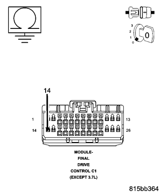
Disconnect the Front Differential Solenoid harness connector.
Disconnect the Rear Differential Solenoid harness connector.
Measure the resistance between ground and the (T301) Switch Battery Solenoid Supply circuit in the FDCM C1 harness connector.
Is the resistance below 100 ohms?
Yes
- Repair the short to ground in the (T301) Switch Battery Solenoid Supply circuit.
- Perform FDCM VERIFICATION TEST.
No
- Go To 4
4. FRONT DIFFERENTIAL SOLENOID OPEN
Measure the resistance of the Front Differential Solenoid at the component side.
Is the resistance above 50 ohms?
Yes
- Inspect the Front Differential Solenoid jumper harness connector, repair/replace as necessary. If OK, replace the shorted Front Differential Solenoid in accordance with the Service Information.
- Perform FDCM VERIFICATION TEST.
No
- Go To 5
5. REAR DIFFERENTIAL SOLENOID OPEN
Measure the resistance of the Front Differential Solenoid at the component side.
Is the resistance above 50 ohms?
Yes
- Inspect the Rear Differential Solenoid jumper harness connector, repair/replace as necessary. If OK, replace the shorted Rear Differential Solenoid in accordance with the Service Information.
- Perform FDCM VERIFICATION TEST.
No
- Go To 6
6. TRANSFER CASE MOTOR OPEN
Measure the resistance of the Transfer Case Motor at the component side.
Is the resistance above 50 ohms?
Yes
- Replace the shorted Transfer Case Motor in accordance with the Service Information.
- Perform FDCM VERIFICATION TEST.
No
- Go To 7
7. FDCM
NOTE: Before continuing, check the FDCM harness connector terminals for corrosion, damage, or terminal push out. Repair as necessary.
Using the schematics as a guide, inspect the wire harness and connectors. Pay particular attention to all Power and Ground circuits.
Were there any problems found?
Yes
- Repair as necessary.
- Perform FDCM VERIFICATION TEST
No
- Replace and program the Final Drive Control Module in accordance with Service Information.
- Perform FDCM VERIFICATION TEST.
8. INTERMITTENT WIRING AND CONNECTORS
The conditions necessary to set this DTC are not present at this time.
Using the schematics as a guide, inspect the wiring and connectors specific to this circuit.
Wiggle test the wiring harness and connectors while checking for shorted and open circuits.
Using the scan tool, monitor the data related to this circuit while performing the wiggle test. Look for the data to change or for the DTC to reset.
Were there any problems found?
Yes
- Repair as necessary.
- Perform FDCM VERIFICATION TEST.
No
- Test Complete.