VALVES & SEATS - INTAKE/EXHAUST
DESCRIPTION
The valves are made of heat resistant steel and have chrome plated stems to prevent scuffing. Each valve is actuated by a roller rocker arm which pivots on a stationary lash adjuster. All valves use three bead lock keepers to retain the springs and promote valve rotation.
STANDARD PROCEDURE - REFACING
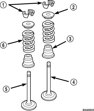
NOTE: Valve seats that are worn or burned can be reworked, provided that correct angle and seat width are maintained. Otherwise the cylinder head must be replaced.
NOTE: When refacing valves (4) and valve seats, it is important that the correct size valve guide pilot be used for reseating stones. A true and complete surface must be obtained.
1. Using a suitable dial indicator measure the center of the valve seat. Total run out must not exceed 0.051 mm (0.002 in).
2. Apply a small amount of Prussian blue to the valve seat, insert the valve into the cylinder head, while applying light pressure on the valve rotate the valve. Remove the valve and examine the valve face. If the blue is transferred below the top edge of the valve face, lower the valve seat using a 15 degree stone. If the blue is transferred to the bottom edge of the valve face, raise the valve seat using a 65 degree stone.
3. When the seat is properly positioned the width of the intake seat must be 1.75 - 2.36 mm (0.0689 - 0.0928 in.) and the exhaust seat must be 1.71 - 2.32 mm (0.0673 - 0.0911 in.).
4. Check the valve spring (6) installed height after refacing the valve and seat. The installed height for both intake and exhaust valve springs must not exceed 40.74 mm (1.6039 in.) .
5. The valve seat and valve face must maintain a face angle of 44.5 - 45 ° angle .
REMOVAL
NOTE: The cylinder heads must be removed in order to peform this procedure.
1. Remove rocker arms and lash adjusters. Refer to procedures in this section.
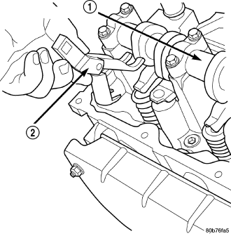
2. Remove the camshaft bearing caps and the camshaft.
NOTE: All eight valve springs and valves are removed in the same manner; this procedure only covers one valve and valve spring.
3. Using Special Tool C-3422–B or C-3422–C Valve Spring Compressor and Special tool 8519 Adapter, compress the valve spring.
NOTE: It may be necessary to tap the top of the valve spring to loosen the spring retainers locks enough to be removed.
4. Remove the two spring retainer lock halves.
NOTE: the valve spring is under tension use care when releasing the valve spring compressor.
5. Remove the valve spring compressor.
6. Remove the spring retainer, and the spring.
NOTE: Check for sharp edges on the keeper grooves. Remove any burrs from the valve stem before removing the valve from the cylinder head.
7. Remove the valve from the cylinder head.
NOTE: The valve stem seals are common between intake and exhaust.
8. Remove the valve stem seal. Mark the valve for proper installation.
TESTING VALVE SPRINGS
NOTE: Whenever the valves are removed from the cylinder head it is recommended that the valve springs be inspected and tested for reuse.
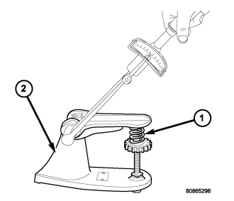
Inspect the valve springs for physical signs of wear or damage. Turn table of tool C-647 until surface is in line with the 40.12 mm (1.579 in.) mark on the threaded stud and the zero mark on the front. Place spring over the stud on the table and lift compressing lever to set tone device. Pull on torque wrench until Ping is heard. Take reading on torque wrench at this instant. Multiply this reading by two. This will give the spring load at test length. Fractional measurements are indicated on the table for finer adjustments. Refer to Specifications Section to obtain specified height and allowable tensions. Replace any springs that do not meet specifications.
INSTALLATION
1. Coat the valve stem with clean engine oil and insert it into the cylinder head.
2. Install the valve stem seal. make sure the seal is fully seated and that the garter spring at the top of the seal is intact.
3. Install the spring and the spring retainer .
4. Using the valve spring compressor, compress the spring and install the two valve spring retainer halves.
5. Release the valve spring compressor and make sure the two spring retainer halves and the spring retainer are fully seated.
6. lubricate the camshaft journal with clean engine oil then Position the camshaft (with the sprocket dowel on the left camshaft at 11 o'clock and the right camshaft at 12 o'clock), then position the camshaft bearing caps.
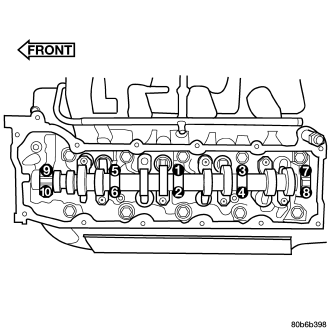
7. Install the camshaft bearing cap retaining bolts. Tighten the bolts 11 N·m (100 in. lbs.) in ½ turn increments in the sequence shown .
8. Position the hydraulic lash adjusters and rocker arms .