PISTON & CONNECTING ROD
DESCRIPTION
CAUTION: Do not use a metal stamp to mark connecting rods as damage may result, instead use ink or a scratch awl.
The pistons are made of a high strength aluminum alloy. Piston skirts are coated with a solid lubricant (Molykote) to reduce friction and provide scuff resistance. The piston top ring groove and land is anodized. The connecting rods are made of forged powdered metal, with a “fractured cap” design. A pressed fit piston pin is used to attach the piston and connecting rod.
STANDARD PROCEDURE - PISTON FITTING
1. To correctly select the proper size piston, a cylinder bore gauge, capable of reading in 0.003 mm ( .0001 in.) INCREMENTS is required. If a bore gauge is not available, do not use an inside micrometer.
2. Measure the inside diameter of the cylinder bore at a point 38.0 mm (1.5 inches) below top of bore. Start perpendicular (across or at 90 degrees) to the axis of the crankshaft at point A and then take an additional bore reading 90 degrees to that at point B.
3. The coated pistons will be serviced with the piston pin and connecting rod pre-assembled. The piston-rod assembly is specific for the left cylinder bank ( odd numbered) and the right cylinder bank ( even numbered) and must not be interchanged.
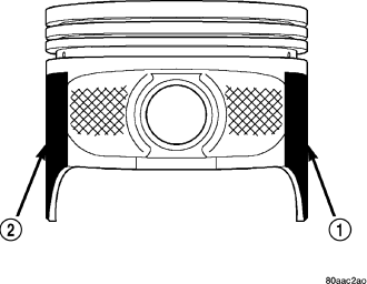
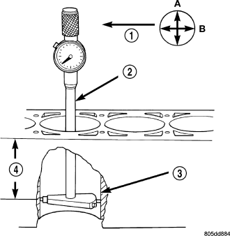
4. The coating material is applied to the piston after the final piston machining process. Measuring the outside diameter of a coated piston will not provide accurate results . Therefore measuring the inside diameter of the cylinder bore with a dial Bore Gauge is MANDATORY. To correctly select the proper size piston, a cylinder bore gauge capable of reading in 0.003 mm (.0001 in.) increments is required.
5. Piston installation into the cylinder bore requires slightly more pressure than that required for non-coated pistons. The bonded coating on the piston will give the appearance of a line-to-line fit with the cylinder bore.
REMOVAL
1. Disconnect negative cable from battery.
2. Remove the following components:
- Oil pan and gasket/windage tray (Refer to 9 - ENGINE/LUBRICATION/OIL PAN - REMOVAL).
- Cylinder head covers (Refer to 9 - ENGINE/CYLINDER HEAD/CYLINDER HEAD COVER(S) - REMOVAL) and (Refer to 9 - ENGINE/CYLINDER HEAD/CYLINDER HEAD COVER(S) - REMOVAL).
- Timing chain cover (Refer to 9 - ENGINE/VALVE TIMING/TIMING BELT / CHAIN COVER(S) - REMOVAL).
- Cylinder head(s) (Refer to 9 - ENGINE/CYLINDER HEAD - REMOVAL) and (Refer to 9 - ENGINE/CYLINDER HEAD - REMOVAL).
3. If necessary, remove top ridge of cylinder bores with a reliable ridge reamer before removing pistons from cylinder block. Be sure to keep tops of pistons covered during this operation. Pistons and connecting rods must be removed from top of cylinder block. When removing piston and connecting rod assemblies from the engine, rotate crankshaft so the each connecting rod is centered in cylinder bore.
CAUTION: DO NOT use a number stamp or a punch to mark connecting rods or caps, as damage to connecting rods could occur
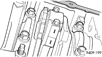
NOTE: Connecting rods and bearing caps are not interchangeable and should be marked before removing to ensure correct reassembly.
4. Mark connecting rod and bearing cap positions using a permanent ink marker or scribe tool .
CAUTION: Care must be taken not to damage the fractured rod and cap joint face surfaces, as engine damage may occur.
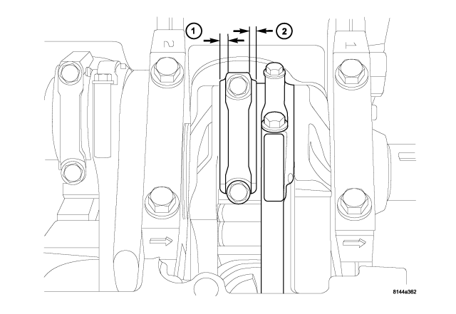
5. Remove connecting rod cap. Install Special Tool 8507 Connecting Rod Guides into the connecting rod being removed. Remove piston from cylinder bore. Repeat this procedure for each piston being removed.
CAUTION: Care must be taken not to nick crankshaft journals, as engine damage may occur
6. Immediately after piston and connecting rod removal, install bearing cap on the mating connecting rod to prevent damage to the fractured cap and rod surfaces.
7. Carefully remove piston rings from piston(s), starting from the top ring down.
CLEANING
CAUTION: DO NOT use a wire wheel or other abrasive cleaning devise to clean the pistons or connecting rods. The pistons have a Moly coating, this coating must not be damaged.
1. Using a suitable cleaning solvent clean the pistons in warm water and towel dry.
2. Use a wood or plastic scraper to clean the ring land grooves.
CAUTION: DO NOT remove the piston pin from the piston and connecting rod assembly.
INSPECTION
Check the connecting rod journal for excessive wear, taper and scoring (Refer to 9 - ENGINE/ENGINE BLOCK/CONNECTING ROD BEARINGS - STANDARD PROCEDURE).
Check the connecting rod for signs of twist or bending.
Check the piston for taper and elliptical shape before it is fitted into the cylinder bore (Refer to 9 - ENGINE/ENGINE BLOCK/PISTON & CONNECTING ROD - STANDARD PROCEDURE).
Check the piston for scoring, or scraping marks in the piston skirts. Check the ring lands for cracks and/or deterioration.
INSTALLATION
1. Before installing piston and connecting rod assemblies into the bore, install the piston rings (Refer to 9 - ENGINE/ENGINE BLOCK/PISTON RINGS - STANDARD PROCEDURE) .
2. Immerse the piston head and rings in clean engine oil. Position a ring compressor over the piston and rings. Tighten ring compressor. Ensure position of rings do not change during this operation.
3. Position bearing onto connecting rod. Lubricate bearing surface with clean engine oil.
4. Install Special Tool 8507 Connecting Rod Guides into connecting rod bolt threads.
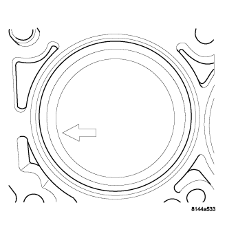
5. The pistons are marked on the piston pin bore surface with an raised “F” or arrow on top of piston indicating installation position. This mark must be pointing toward the front of engine on both cylinder banks.
6. Wipe cylinder bore clean and lubricate with engine oil.
7. Rotate crankshaft until connecting rod journal is on the center of cylinder bore. Insert rod and piston into cylinder bore and carefully position connecting rod guides over crankshaft journal.
8. Tap piston down in cylinder bore using a hammer handle. While at the same time, guide connecting rod into position on rod journal.
CAUTION: Connecting Rod Bolts are Torque to Yield Bolts and Must Not Be Reused. Always replace the Rod Bolts whenever they are loosened or removed.
9. Lubricate rod bolts and bearing surfaces with engine oil. Install connecting rod cap and bearing. Tighten bolts to 21 N·m (15 ft. lbs.) plus a 90° turn.
10. Install the following components:
- Cylinder head(s). (Refer to 9 - ENGINE/CYLINDER HEAD - INSTALLATION).
- Cylinder head covers (Refer to 9 - ENGINE/CYLINDER HEAD/CYLINDER HEAD COVER(S) - INSTALLATION).
- Install the intake manifold.
- Oil pan and gasket/windage tray. (Refer to 9 - ENGINE/LUBRICATION/OIL PAN - INSTALLATION).
11. Fill crankcase with proper engine oil to correct level.
12. Connect negative cable to battery.