VALVES & SEATS - INTAKE/EXHAUST
STANDARD PROCEDURE - REFACING
NOTE: Valve seats that are worn or burned can be reworked, provided that correct angle and seat width are maintained. Otherwise the cylinder head must be replaced.
NOTE: When refacing valves and valve seats, it is important that the correct size valve guide pilot be used for reseating stones. A true and complete surface must be obtained.
1. Using a suitable dial indicator measure the center of the valve seat Total run out must not exceed 0.051 mm (0.002 in).
2. Apply a small amount of Prussian blue to the valve seat, insert the valve into the cylinder head, while applying light pressure on the valve rotate the valve. Remove the valve and examine the valve face. If the blue is transferred below the top edge of the valve face, lower the valve seat using a 15 degree stone. If the blue is transferred to the bottom edge of the valve face, raise the valve seat using a 65 degree stone.
3. When the seat is properly positioned the width of the intake seat must be 1.18 - 1.62 mm (0.0464 - 0.0637 in.) and the exhaust seat must be 1.48 - 1.92 mm (0.058 - 0.075 in.).
4. Check the valve spring installed height after refacing the valve and seat. The installed height for both intake and exhaust valve springs must not exceed 46.0 mm (1.81 in.) .
| DESCRIPTION | SPECIFICATION |
| SEAT WIDTH | |
| INTAKE | 1.18 - 1.62 mm |
| (0.0464 - 0.0637 in.) | |
| EXHAUST | 1.48 - 1.92 mm |
| (0.058 - 0.075 in.) | |
| FACE ANGLE | |
| (INT. AND EXT.) | 45° - 45½° |
| SEAT ANGLE | |
| (INT. AND EXT.) | 44½° - 45° |
5. The valve seat must maintain an angle of 44.5 – 45.0 degrees angle.
6. The valve face must maintain a face angle of 45.0 – 45.5 degrees angle .
REMOVAL
1. Remove the cylinder head (Refer to 9 - ENGINE/CYLINDER HEAD - REMOVAL).
2. Compress valve springs using Valve Spring Compressor Tool special tool # C-3422 and adapter 8464.
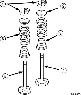
3. Remove valve retaining locks, valve spring retainers, valve stem seals and valve springs.
4. Before removing valves, remove any burrs from valve stem lock grooves to prevent damage to the valve guides. Identify valves to ensure installation in original location.
INSTALLATION
1. Clean valves thoroughly. Discard burned, warped and cracked valves.
2. Remove carbon and varnish deposits from inside of valve guides with a reliable guide cleaner.
3. Measure valve stems for wear. If wear exceeds 0.051 mm (0.002 inch), replace the valve.
4. Coat valve stems with lubrication oil and insert them in cylinder head.
5. If valves or seats are reground, check valve stem height. If valve is too long, replace cylinder head.
6. Install new seals on all valve guides. Install valve springs and valve retainers.
7. Compress valve springs with Valve Spring Compressor Tool special tool # C- 3422 and adapter 8464, install locks and release tool. If valves and/or seats are ground, measure the installed height of springs. Make sure the measurement is taken from bottom of spring seat in cylinder head to the bottom surface of spring retainer.
8. Install cylinder head (Refer to 9 - ENGINE/CYLINDER HEAD - INSTALLATION).