P0404-EGR POSITION SENSOR RATIONALITY OPEN
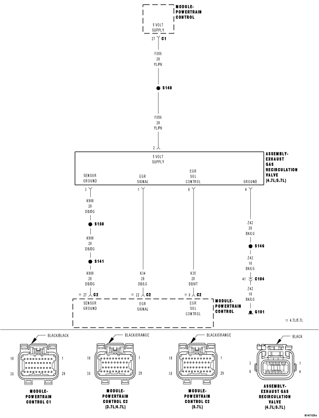
For a complete wiring diagram Refer to Section 8W.
Theory of Operation
The EGR valve has a position sensor and the EGR position rationality is designed to make sure that the valve moves freely within its operating range. Closed valve position reference check verifies that the valve is within its allowable upper and lower limits. The EGR position rationality test looks for a sustained error relative to commanded valve position.
- When Monitored:
Engine running.
- Set Condition:
The EGR flow or valve movement is not what is expected. A rationality error has been detected fro the EGR Close Position Performance. Two trip fault.
| Possible Causes |
| EXCESSIVE RESISTANCE IN THE (F856) 5-VOLT SUPPLY CIRCUIT |
| (K35) EGR SOLENOID CONTROL CIRCUIT |
| (K34) EGR SENSOR SIGNAL CIRCUIT OPEN |
| (K34) EGR SENSOR SIGNAL CIRCUIT SHORTED TO GROUND |
| (K900) SENSOR GROUND CIRCUIT OPEN |
| EGR SOLENOID ASSEMBLY |
| PCM |
Always perform the Pre-Diagnostic Troubleshooting procedure before proceeding. (Refer to 9 - ENGINE - DIAGNOSIS AND TESTING).
Diagnostic Test
1. ACTIVE DTCStart the engine.
Allow the engine to reach normal operating temperature.
With a scan tool, select View DTCs.
NOTE: It may be necessary to drive the vehicle to meet the conditions to set this DTC, try to repeat the conditions in which the fault originally set by reviewing the Freeze Frame data.
Is the DTC Active or Pending at this time?
Yes
- Go To 2
No
- Refer to the INTERMITTENT CONDITION Diagnostic Procedure.
- Perform the POWERTRAIN VERIFICATION TEST. (Refer to 9 - ENGINE - STANDARD PROCEDURE)
2. EGR POSITION VOLTAGE
NOTE: Diagnose all other EGR DTC(s) before continuing.
Start the engine.
With a scan tool, read the EGR Position Sensor voltage.
Choose a conclusion that best matches the EGR voltage reading.
Below 3.5 volts
- Go To 3
Between 3.5 volts to 4.3 volts
- Go To 5
Above 4.3 volts
- Go To 6
3. EXCESSIVE RESISTANCE IN THE (F856) 5-VOLT SUPPLY CIRCUIT
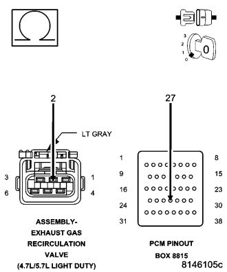
Turn the ignition off.
Disconnect the EGR Solenoid harness connector.
Disconnect the C1 and C2 PCM harness connectors.
CAUTION: Do not probe the PCM harness connectors. Probing the PCM harness connectors will damage the PCM terminals resulting in poor terminal to pin connection. Install Miller Special Tool #8815 to perform diagnosis.
Measure the resistance of the (F856) 5-volt Supply circuit from the EGR Solenoid harness connector to the appropriate terminal of special tool #8815.
Is the resistance below 5.0 ohms?
Yes
- Go To 4
No
- Repair the excessive resistance in the (F856) 5-volt Supply circuit.
- Perform the POWERTRAIN VERIFICATION TEST. (Refer to 9 - ENGINE - STANDARD PROCEDURE)
4. (K34) EGR SENSOR SIGNAL CIRCUIT SHORTED TO GROUND
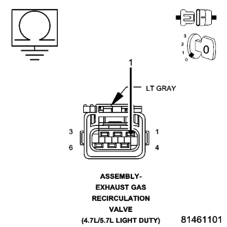
Measure the resistance between ground and the (K34) EGR Sensor Signal circuit in the EGR Solenoid harness connector.
Is the resistance below 5.0 ohms?
Yes
- Repair the short to ground in the (K34) EGR Sensor Signal circuit.
- Perform the POWERTRAIN VERIFICATION TEST. (Refer to 9 - ENGINE - STANDARD PROCEDURE)
No
- Replace the EGR Assembly.
- Perform the POWERTRAIN VERIFICATION TEST. (Refer to 9 - ENGINE - STANDARD PROCEDURE)
5. (K35) EGR SOLENOID CONTROL CIRCUIT
Ignition on, engine not running.
With the scan tool, actuate the EGR Solenoid.
Allow the EGR Solenoid to actuate for at least 15 seconds.
Feel the EGR Solenoid for operation.
Stop actuation.
Does EGR Solenoid operate while actuating and then turn off when actuation test is stopped?
a. Yes
- Refer to the INTERMITTENT CONDITION Diagnostic Procedure.
- Perform the POWERTRAIN VERIFICATION TEST. (Refer to 9 - ENGINE - STANDARD PROCEDURE)
No
- Refer to the P0403-EGR Control Circuit diagnostic procedure and continue.
- Perform the POWERTRAIN VERIFICATION TEST. (Refer to 9 - ENGINE - STANDARD PROCEDURE)
6. (K34) EGR SENSOR SIGNAL CIRCUIT
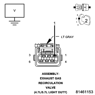
Turn the ignition off.
Disconnect the EGR Solenoid harness connector.
Ignition on, engine not running.
Measure the voltage of the (K34) EGR Sensor Signal circuit in the EGR Solenoid harness connector.
Is the voltage above 4.30 volts?
Yes
- Go To 7
No
- Go To 8
7. (K900) SENSOR GROUND CIRCUIT OPEN
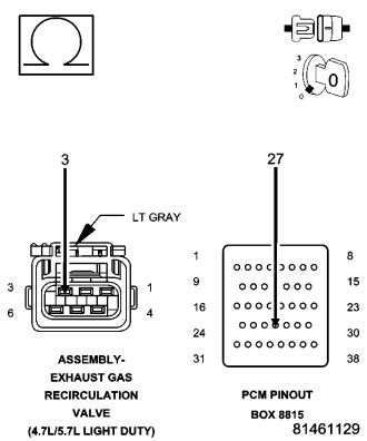
Turn the ignition off.
Disconnect the C2 PCM harness connector.
CAUTION: Do not probe the PCM harness connectors. Probing the PCM harness connectors will damage the PCM terminals resulting in poor terminal to pin connection. Install Miller Special Tool #8815 to perform diagnosis.
Measure the resistance of the (K900) Sensor ground circuit from the EGR Solenoid harness connector to the appropriate terminal of special tool #8815.
Is the resistance below 5.0 ohms?
Yes
- Replace the EGR Assembly.
- Perform the POWERTRAIN VERIFICATION TEST. (Refer to 9 - ENGINE - STANDARD PROCEDURE)
No
- Repair the open in the (K900) Sensor ground circuit.
- Perform the POWERTRAIN VERIFICATION TEST. (Refer to 9 - ENGINE - STANDARD PROCEDURE)
8. (K34) EGR SENSOR SIGNAL CIRCUIT OPEN
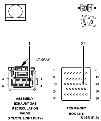
Turn the ignition off.
Disconnect the C2 PCM harness connector.
CAUTION: Do not probe the PCM harness connectors. Probing the PCM harness connectors will damage the PCM terminals resulting in poor terminal to pin connection. Install Miller Special Tool #8815 to perform diagnosis.
Measure the resistance of the (K34) EGR Sensor Signal circuit from the EGR Solenoid harness connector to the appropriate terminal of special tool #8815.
Is the resistance below 5.0 ohms?
Yes
- Go To 9
No
- Repair the open in the (K34) EGR Sensor Signal circuit.
- Perform the POWERTRAIN VERIFICATION TEST. (Refer to 9 - ENGINE - STANDARD PROCEDURE)
9. PCM
NOTE: Before continuing, check the PCM harness connector terminals for corrosion, damage, or terminal push out. Repair as necessary.
Using the schematics as a guide, inspect the wire harness and connectors. Pay particular attention to all Power and Ground circuits.
Were there any problems found?
Yes
- Repair as necessary.
- Perform the POWERTRAIN VERIFICATION TEST. (Refer to 9 - ENGINE - STANDARD PROCEDURE)
No
- Replace and program the Powertrain Control Module per Service Information.
- Perform the POWERTRAIN VERIFICATION TEST. (Refer to 9 - ENGINE - STANDARD PROCEDURE)