P0586-SPEED CONTROL VENT CONTROL CIRCUIT
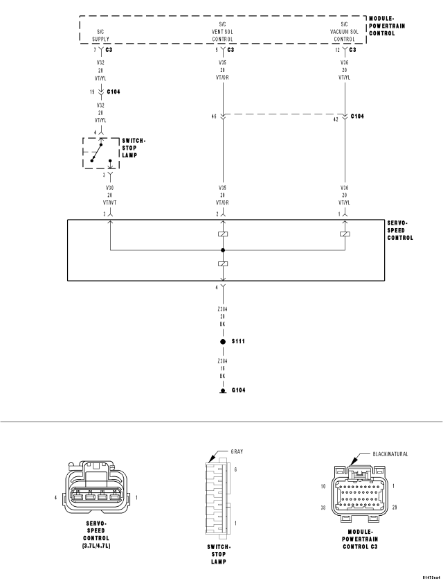
For a complete wiring diagram Refer to Section 8W.
- When Monitored:
Ignition on and battery voltage greater than 10 volts.
- Set Condition:
An open or shorted condition detected in the Speed control vent solenoid control circuit. One Trip Fault. Three good trips to turn off the MIL.
| Possible Causes |
| (V32) S/C SUPPLY CIRCUIT OPEN |
| (V32) S/C SUPPLY SHORT TO GROUND |
| (V35) S/C VENT SOL CONTROL CIRCUIT SHORTED TO GROUND |
| (V35) S/C VENT SOL CONTROL CIRCUIT OPEN |
| (Z384) GROUND CIRCUIT OPEN |
| SPEED CONTROL VENT SOLENOID |
| PCM |
Always perform the Pre-Diagnostic Troubleshooting procedure before proceeding. (Refer to 9 - ENGINE - DIAGNOSIS AND TESTING).
Diagnostic Test
1. SPEED CONTROL VENT CONTROLIgnition on, engine not running.
With the scan tool, select View DTCs and record the related Freeze Frame data.
With the scan tool, actuate the Speed Control Vent Solenoid and note operation.
Does the Speed Control Vent Solenoid actuate properly?
Yes
- Refer to the INTERMITTENT CONDITION symptom in the Driveability category.
- Perform the POWERTRAIN VERIFICATION TEST. (Refer to 9 - ENGINE - STANDARD PROCEDURE)
No
- Go To 2
2. (V30) S/C BRAKE SWITCH OUTPUT CIRCUIT
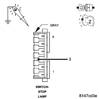
Turn the ignition off.
Disconnect the S/C Servo harness connector.
Ignition on, engine not running.
Using the scan tool, actuate the S/C Vent Solenoid.
Using a test light connected to ground, probe the (V30) S/C Brake Switch Output circuit in the S/C Servo harness connector.
Does the test light illuminate brightly and flash on and off?
Yes
- Go To 5
No
- Go To 3
3. (V32) S/C SUPPLY CIRCUIT
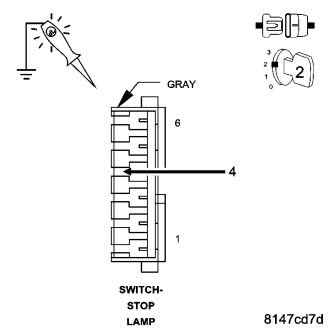
Turn the ignition off.
Connect the S/C Servo harness connector.
Disconnect the Stop Lamp Switch harness connector.
Ignition on, engine not running.
Using the scan tool, actuate the S/C Vent Solenoid.
Using a test light connected to ground, probe the (V32) S/C Supply circuit in the Stop Lamp Switch harness connector.
Does the test light illuminate brightly?
Yes
- Go To 4
No
- Go To 8
4. (Z384) S/C GROUND CIRCUIT OPEN
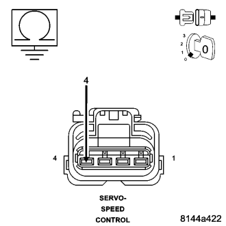
Turn the ignition off.
Disconnect the S/C Servo harness connector.
Measure the resistance of the (Z384) S/C Ground circuit at the S/C Servo harness connector to ground.
Is the resistance below 5.0 ohms?
Yes
- Go To 5
No
- Repair the open in the (Z384) S/C Ground circuit.
- Perform the POWERTRAIN VERIFICATION TEST. (Refer to 9 - ENGINE - STANDARD PROCEDURE)
5. SPEED CONTROL VENT SOLENOID
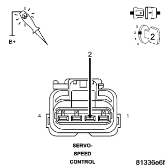
Ignition on, engine not running.
With the scan tool, actuate the Speed Control Vent Solenoid.
Using a 12-volt test light connected to battery voltage, probe the (V36) S/C Vent Control circuit.
Does the test light illuminate brightly and flash on and off?
Yes
- Replace the Speed Control Servo.
- Perform the POWERTRAIN VERIFICATION TEST. (Refer to 9 - ENGINE - STANDARD PROCEDURE)
No
- Go To 6
6. (V35) S/C VENT CONTROL CIRCUIT OPEN
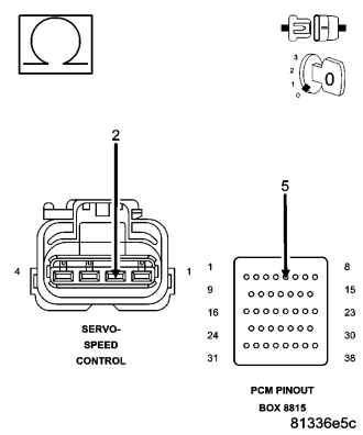
Turn the ignition off.
Disconnect the C3 PCM harness connector.
CAUTION: Do not probe the PCM harness connectors. Probing the PCM harness connectors will damage the PCM terminals resulting in poor terminal to pin connection. Install Miller Special Tool #8815 to perform diagnosis.
Measure the resistance of the (V35) S/C Vent Sol Control circuit from the Speed Control Servo harness connector to the appropriate terminal of special tool # 8815.
Is the resistance below 5.0 ohms?
Yes
- Go To 7
No
- Repair the open/high resistance in the (V35) S/C Vent Sol Control circuit.
- Perform the POWERTRAIN VERIFICATION TEST. (Refer to 9 - ENGINE - STANDARD PROCEDURE)
7. (V35) SPEED CONTROL VENT SOLENOID CONTROL CIRCUIT SHORTED TO GROUND
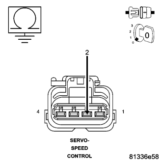
Measure the resistance between ground and the (V35) S/C Vent Solenoid Control circuit at the Speed Control Servo harness connector.
Is the resistance below 100 ohms?
Yes
- Repair the short to ground in the (V35) S/C Vent Sol Control circuit.
- Perform the POWERTRAIN VERIFICATION TEST. (Refer to 9 - ENGINE - STANDARD PROCEDURE)
No
- Go To 10
8. (V32) S/C SUPPLY OPEN
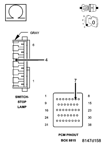
Turn the ignition off.
Disconnect the C3 PCM harness connector.
CAUTION: Do not probe the PCM harness connectors. Probing the PCM harness connectors will damage the PCM terminals resulting in poor terminal to pin connection. Install Miller Special Tool #8815 to perform diagnosis.
Measure the resistance of the (V32) S/C Supply circuit from the Stop Lamp Switch harness connector to the appropriate terminal of special tool #8815.
Is the resistance below 5.0 ohms?
Yes
- Go To 9
No
- Repair the open/high resistance in the (V32) S/C Supply circuit.
- Perform the POWERTRAIN VERIFICATION TEST. (Refer to 9 - ENGINE - STANDARD PROCEDURE)
9. (V32) S/C SUPPLY CIRCUIT SHORTED TO GROUND
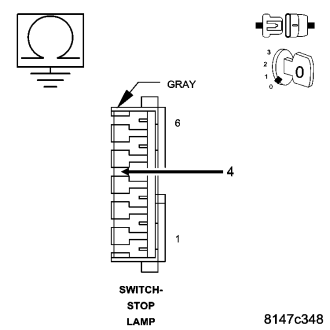
Measure the resistance between ground and the (V32) S/C Supply circuit at the Speed Control Servo harness connector.
Is the resistance below 100 ohms?
Yes
- Repair the short to ground in the (V32) S/C Supply circuit.
- Perform the POWERTRAIN VERIFICATION TEST. (Refer to 9 - ENGINE - STANDARD PROCEDURE)
No
- Go To 10
10. PCM
NOTE: Before continuing, check the PCM harness connector terminals for corrosion, damage, or terminal push out. Repair as necessary.
Were there any problems found?
Yes
- Repair as necessary.
- Perform the POWERTRAIN VERIFICATION TEST. (Refer to 9 - ENGINE - STANDARD PROCEDURE)
No
- Replace and program the Powertrain Control Module per Service Information.
- Perform the POWERTRAIN VERIFICATION TEST. (Refer to 9 - ENGINE - STANDARD PROCEDURE)