FAN-RADIATOR
DESCRIPTION
3.7L ENGINE
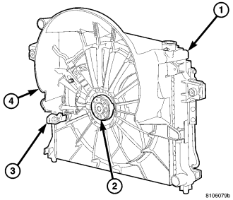
The radiator cooling fan used on the 3.7L engine is an electrical fan and is integral to the fan shroud.
4.7L ENGINE
The radiator cooling fan used on the 4.7L engine is a hybrid design. The hybrid fan system consist of a low speed viscous driven mechanical fan and a electrical fan.
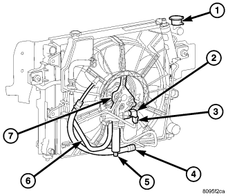
| HYDRAULIC RADIATOR COOLING FAN AND FAN DRIVE - 5.7L |
| 1 - RADIATOR |
| 2 - HYDRAULIC FAN MOTOR SOLENOID |
| 3 - ELECTRICAL CONNECTOR |
| 4 - HIGH PRESSURE LINE FROM HYDRAULIC FAN MOTOR TO STEERING GEAR |
| 5 - HIGH PRESSURE LINE |
| 6 - RETURN LINE |
| 7 - FAN MOTOR |
5.7L ENGINE
The 5.7L hydraulic cooling fan is integral to the fan shroud and is located between the radiator and the engine .
The power steering pump supplies the hydraulic fluid and pressure to rotate the cooling fan blade, while the electrical part of the fan is controlled by the FCM.
The hydraulic fan drive (motor) consists of the three major following components:
- Steering flow control valve
- Fan control valve
- Two stage G-rotor hydraulic drive
The hydraulic fan and drive is not serviceable. Therefore any failure of the fan blade, hydraulic fan drive or fan shroud requires replacement of the fan module because the fan blade and hydraulic fan drive are matched and balanced as a system and servicing either separately would disrupt this balance.
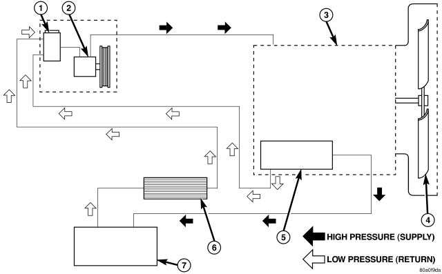
| HYDRAULIC FAN FLUID FLOW CIRCUIT |
| 1 - POWER STEERING RESERVOIR |
| 2 - POWER STEERING PUMP |
| 3 - HYDRAULIC FAN DRIVE ASSEMBLY |
| 4 - FAN BLADE |
| 5 - HYDRAULIC FAN CONTROL SOLENOID |
| 6 - POWER STEERING OIL COOLER |
| 7 - STEERING GEAR |
For hydraulic fluid routing information refer to flow chart.
CAUTION: Do not attempt to service the hydraulic cooling fan or fan drive separately, they are serviced as an assembly. Failure to do so may cause severe damage to the hydraulic cooling fan assembly.
OPERATION
The hydraulic radiator cooling fan used on the 5.7L and 3.0L Diesel engines replaces both the electric fan and the engine driven mechanical fan. This provides 5.7L and 3.0L Diesel equipped vehicles with heavy trailer towing capability while at the same time reducing unnecessary power drain on both the engine and the vehicles electrical system.
HYDRAULIC FAN STRATEGY
The hydraulic radiator cooling fan is controlled by the FCM. A PWM (Pulse With Modulated) signal from the JTEC controls the fan speed. There are four inputs to the FCM that determine what speed percentage of fan is required by the vehicle. These inputs are:
- Engine Coolant Temperature
- Transmission Oil Temperature
- A/C System Pressure
By monitoring these three parameters, the FCM can determine if cooling airflow is required. If airflow is required, the FCM will slowly ramp up (speed up) the fan speed until the parameter(s) are under control. Once the temperature or pressure is reduced to within operating parameters the fan will ramp up, ramp down, or hold its speed to maintain the temperature / pressure requirements.
NOTE: Even if the FCM is not requesting fan on operation the fan blade will usually spin between 100 and 500 RPM when the vehicle is at idle. This is due to a controlled minimum oil flow requirement through the fan drive motor.
ACTIVATING THE HYDRAULIC FAN WITH THE SCAN TOOL
Under the Engine Systems test heading, there is a subheading. “Hydraulic fan solenoid test”, that has the selections, on/off. Activating the fan with the scan tool will run the fan at 100% duty cycle, which will help troubleshoot any system problems, and also help with the deaeration procedure.
NOTE: Engine must be running to activate the fan with the scan tool.
RADIATOR COOLING FAN HYDRAULIC FLUID PATH
Hydraulic fluid is pumped through the power steering pump, from the pump the fluid travels though a high pressure delivery line to the fan drive motor. As fluid is diverted through the G-rotors, rotational motion is created as fluid moves from the high-pressure (inlet) side of the motor to the low-pressure (outlet) side. Fluid exiting the drive motor is divided into two paths. Path one continues through a high pressure delivery line to the vehicles steering gear to provide steering assist. and path two sends fluid back to the power steering pump through a low pressure line. Fluid exits the steering gear under low pressure and travels through a low pressure line to the power steering fluid cooler to be cooled before being returned back the power steering fluid reservoir.
NOTE: There is a steering flow control valve located in the fan drive motor. This valve operates like the flow control valve found in the typical power steering pump. Because of the design of the valve steering assist can not be effected by the radiator cooling fan even during fan drive failure.
DIAGNOSIS AND TESTING-ELECTRIC COOLING FAN
The powertrain control module (PCM) will enter a diagnostic trouble code (DTC) in memory if it detects a problem in the auxiliary cooling fan relay or circuit. (Refer to 25 - EMISSIONS CONTROL - DESCRIPTION).
If the electric cooling fan is inoperative, check the 15A fuse in the junction block and the 40A fuse in the Power Distribution Center (PDC) with a 12 volt test lamp or DVOM. Refer to the inside of the PDC cover for the exact location of the fuse. If fuses are okay, refer to ELECTRICAL SCHEMATICS for the cooling fan and relay circuit schematic.
CLEANING
Clean the fan blades using a mild soap and water. Do not use an abrasive to clean the blades.INSPECTION
WARNING: DO NOT ATTEMPT TO BEND OR STRAIGHTEN FAN BLADES IF FAN IS NOT WITHIN SPECIFICATIONS.
CAUTION: If fan blade assembly is replaced because of mechanical damage, water pump and viscous fan drive should also be inspected. These components could have been damaged due to excessive vibration.
1. Remove fan blade assembly from viscous fan drive unit (four bolts).
2. Lay fan on a flat surface with leading edge facing down. With tip of blade touching flat surface, replace fan if clearance between opposite blade and surface is greater than 2.0 mm (.090 inch). Rocking motion of opposite blades should not exceed 2.0 mm (.090 inch). Test all blades in this manner.
3. Inspect fan assembly for cracks, bends, loose rivets or broken welds. Replace fan if any damage is found.