KNUCKLE
DESCRIPTION
The knuckle is a single casting with legs machined for the upper and lower ball joints. The knuckle also has machined mounting locations for the front brake calipers and hub bearing.
OPERATION
The steering knuckle pivot between the upper and lower ball joint. Steering linkage attached to the knuckle allows the vehicle to be steered.
REMOVAL
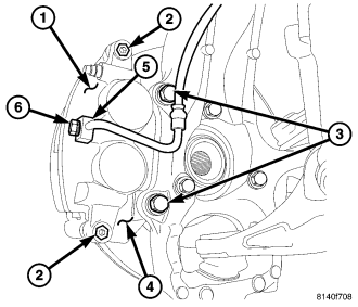
1. Raise and support the vehicle.
2. Remove the tire and wheel assembly.
CAUTION: Never allow the disc brake caliper to hang from the brake hose. Damage to the brake hose will result. Provide a suitable support to hang the caliper securely.
3. Remove the brake caliper (1).
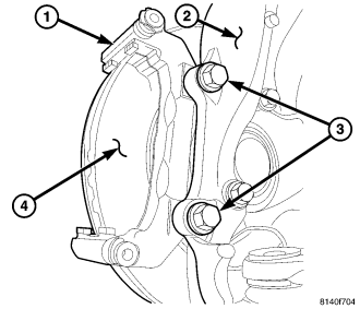
4. Remove the caliper adapter (1). (Refer to 5 - BRAKES/HYDRAULIC/MECHANICAL/DISC BRAKE CALIPER ADAPTER - REMOVAL).
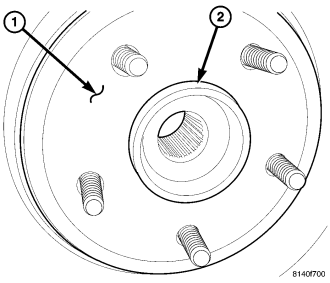
5. Remove the o-ring (2) and discard then remove disc brake rotor (1). (Refer to 5 - BRAKES/HYDRAULIC/MECHANICAL/ROTORS - REMOVAL).
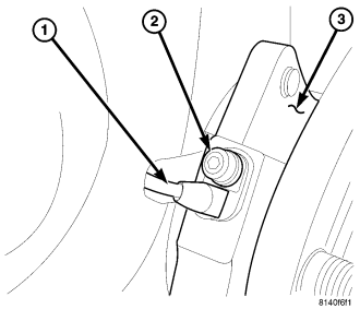
6. Remove the wheel speed sensor bolt (2) and disconnect the wire from the retaining clips from the knuckle (Refer to 5 - BRAKES/ELECTRICAL/FRONT WHEEL SPEED SENSOR - REMOVAL).
7. Remove the axle shaft nut. (if equipped with four wheel drive)
8. Remove the hub/bearing (3). (Refer to 2 - SUSPENSION/FRONT/HUB / BEARING - REMOVAL).
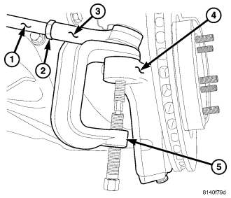
9. Remove the outer tie rod end retaining nut.
10. Seperate the outer tie rod end (3) from the steering knuckle using special tool 8677(5). (Refer to 19 - STEERING/LINKAGE/TIE ROD END - REMOVAL).
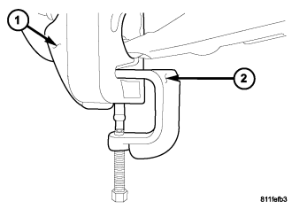
11. Remove the lower ball joint nut.
12. Seperate the lower ball joint from the knuckle (1) using tool C–4150A (2).
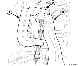
13. Remove the upper ball joint nut.
14. Seperate the upper ball joint (2) from the knuckle (3) using tool 8677 (1).
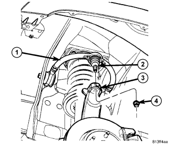
15. Remove the knuckle (3) from the vehicle.
INSTALLATION
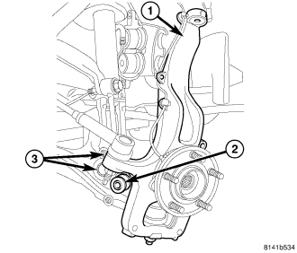
1. Install the knuckle (1) to the vehicle.
2. Install the lower ball joint into the knuckle.
3. Install the lower ball joint nut. Tighten the nut to 95 N·m (70 ft.lbs.).
4. Install the upper ball joint (2) into the knuckle (3)
5. Install the upper ball joint nut (4). Tighten the nut to 95 N·m (70 ft.lbs.).
6. Install the outer tie rod end to the steering knuckle. (Refer to 19 - STEERING/LINKAGE/TIE ROD END - INSTALLATION).
7. Install the hub/bearing (3), Tighten to 115 N·m (85 ft.lbs.). (Refer to 2 - SUSPENSION/FRONT/HUB / BEARING - INSTALLATION).
8. Install the axle shaft nut. Tighten the nut to 135 N·m (96 ft.lbs.).(if equipped with four wheel drive).
9. Install the wheel speed sensor (2) and reclip the wire to the knuckle. (Refer to 5 - BRAKES/ELECTRICAL/FRONT WHEEL SPEED SENSOR - INSTALLATION).
10. Install the disc brake rotor (1). (Refer to 5 - BRAKES/HYDRAULIC/MECHANICAL/ROTORS - INSTALLATION).
11. Install the caliper adapter (1) . (Refer to 5 - BRAKES/HYDRAULIC/MECHANICAL/DISC BRAKE CALIPER ADAPTER - INSTALLATION).
12. Install the tire and wheel assembly. (Refer to 22 - TIRES/WHEELS/WHEELS - STANDARD PROCEDURE).
13. Perform wheel alignment (Refer to 2 - SUSPENSION/WHEEL ALIGNMENT - STANDARD PROCEDURE).