*A/C HEATER CONTROL WILL NOT ENTER DIAGNOSTIC MODE (MTC)
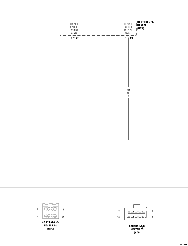
For a complete wiring diagram Refer to Section 8W.
Theory of Operation
An active DTC 33 will prevent the control from entering diagnostic mode and performing certain diagnostic functions, it will also prevent proper A/C mode switch and status indicator function. An active DTC 34 will prevent the control from performing certain diagnostic functions and it will prevent proper EBL mode switch and status indicator function. In addition, a short or an open (C41) Blower Switch Position Signal circuit will also prevent the control from entering diagnostic mode. For additional information about the A/C Heater Control's on-board diagnostics, refer to 24 - HEATING & AIR CONDITIONING - DIAGNOSIS AND TESTING.
| Possible Causes |
| OBJECT HOLDING A/C MODE SWITCH / EBL MODE SWITCH IN A PUSHED POSITION |
| SUBSTANCE CAUSING A/C MODE SWITCH / EBL MODE SWITCH TO GET STUCK IN A PUSHED POSITION |
| (C41) BLOWER SWITCH POSITION SIGNAL CIRCUIT SHORTED TO VOLTAGE |
| (C41) BLOWER SWITCH POSITION SIGNAL CIRCUIT SHORTED TO (C121) SENSOR GROUND CIRCUIT |
| (C41) BLOWER SWITCH POSITION SIGNAL CIRCUIT SHORTED TO GROUND |
| (C41) BLOWER SWITCH POSITION SIGNAL CIRCUIT OPEN |
| A/C STATUS INDICATOR / EBL STATUS INDICATOR INOPERATIVE |
| A/C HEATER CONTROL |
Diagnostic Test
1. INSPECT THE A/C HEATER CONTROL FOR DAMAGETurn the ignition off.
Inspect the A/C Heater Control for damage.
Is the A/C Heater Control damaged?
Yes
- Replace the A/C Heater Control in accordance with the Service Information.
- Perform BODY VERIFICATION TEST – VER 1. (Refer to 8 - ELECTRICAL/ELECTRONIC CONTROL MODULES - STANDARD PROCEDURE).
No
- Go To 2
2. INSPECT FOR OBJECT OR SUBSTANCE CAUSING THE A/C MODE SWITCH OR EBL MODE SWITCH TO STAY OR STICK IN A PUSHED POSITION
Inspect the A/C Heater Control for anything that would cause the A/C mode switch or the EBL mode switch to stay or stick in a pushed position.
Is anything present that would cause the A/C mode switch or EBL mode switch to stay or stick in a pushed position?
Yes
- Repair as necessary.
- Perform BODY VERIFICATION TEST – VER 1. (Refer to 8 - ELECTRICAL/ELECTRONIC CONTROL MODULES - STANDARD PROCEDURE).
No
- Go To 3
3. CHECK THE (C41) BLOWER SWITCH POSITION SIGNAL CIRCUIT VOLTAGE
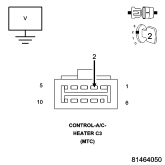
Disconnect the A/C Heater Control C3 harness connector.
Turn the ignition on.
Measure the voltage of the (C41) Blower Switch Position Signal circuit.
What is the voltage?
Below 4.8 Volts
- Go To 4
Above 5.2 Volts
- Go To 7
4.8 Volts To 5.2 Volts
- Go To 8
4. CHECK THE (C41) BLOWER SWITCH POSITION SIGNAL CIRCUIT FOR A SHORT TO THE (C121) SENSOR GROUND CIRCUIT
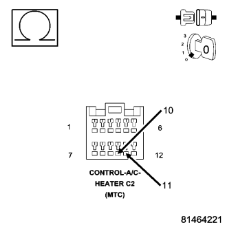
Turn the ignition off.
Disconnect the A/C Heater Control C2 harness connector.
Measure the resistance between the (C41) Blower Switch Position Signal circuit and the (C121) Sensor Ground circuit in the A/C Heater Control C2 harness connector.
Is the resistance below 10K ohms?
Yes
- Repair the (C41) Blower Switch Position Signal circuit for a short to the (C121) Sensor Ground circuit.
- Perform BODY VERIFICATION TEST - VER 1. (Refer to 8 - ELECTRICAL/ELECTRONIC CONTROL MODULES - STANDARD PROCEDURE).
No
- Go To 5
5. CHECK THE (C41) BLOWER SWITCH POSITION SIGNAL CIRCUIT FOR A SHORT TO GROUND
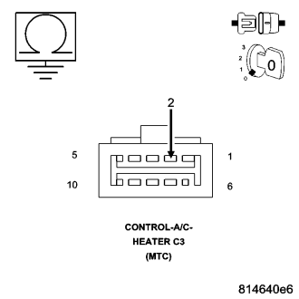
Measure the resistance of the (C41) Blower Switch Position Signal circuit between ground and the A/C Heater Control C3 harness connector.
Is the resistance below 10K ohms?
Yes
- Repair the (C41) Blower Switch Position Signal circuit for a short to ground.
- Perform BODY VERIFICATION TEST - VER 1. (Refer to 8 - ELECTRICAL/ELECTRONIC CONTROL MODULES - STANDARD PROCEDURE).
No
- Go To 6
6. CHECK (C41) BLOWER SWITCH POSITION SIGNAL CIRCUIT FOR AN OPEN
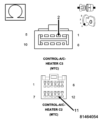
Measure the resistance of the (C41) Blower Switch Position Signal circuit between the A/C Heater Control C2 harness connector and the A/C Heater Control C3 harness connector.
Is the resistance below 5.0 ohms?
Yes
- Replace the A/C Heater Control in accordance with the Service Information.
- Perform BODY VERIFICATION TEST - VER 1. (Refer to 8 - ELECTRICAL/ELECTRONIC CONTROL MODULES - STANDARD PROCEDURE).
No
- Repair the (C41) Blower Switch Position Signal circuit for an open.
- Perform BODY VERIFICATION TEST - VER 1. (Refer to 8 - ELECTRICAL/ELECTRONIC CONTROL MODULES - STANDARD PROCEDURE).
7. CHECK THE (C41) BLOWER SWITCH POSITION SIGNAL CIRCUIT FOR A SHORT TO VOLTAGE
Turn the ignition off.
Disconnect the A/C Heater Control C2 harness connector.
Turn the ignition on.
Measure the voltage of the (C41) Blower Switch Position Signal circuit.
Is the voltage above 0.2 volts?
Yes
- Repair the (C41) Blower Switch Position Signal circuit for a short to voltage.
- Perform BODY VERIFICATION TEST - VER 1. (Refer to 8 - ELECTRICAL/ELECTRONIC CONTROL MODULES - STANDARD PROCEDURE).
No
- Replace the A/C Heater Control in accordance with the Service Information.
- Perform BODY VERIFICATION TEST - VER 1. (Refer to 8 - ELECTRICAL/ELECTRONIC CONTROL MODULES - STANDARD PROCEDURE).
8. CHECK FOR NORMAL A/C MODE SWITCH & STATUS INDICATOR FUNCTION
Turn the ignition off.
Reconnect the A/C Heater Control C3 harness connector.
Turn the ignition on.
Turn the blower control on.
Press the A/C mode switch on and off several times while observing the A/C status indicator.
Does the A/C status indicator turn on and off with respect to the switch position?
Yes
- Go To 9
No
- Replace the A/C Heater Control in accordance with the Service Information.
- Perform BODY VERIFICATION TEST – VER 1. (Refer to 8 - ELECTRICAL/ELECTRONIC CONTROL MODULES - STANDARD PROCEDURE).
9. CHECK FOR NORMAL EBL MODE SWITCH & STATUS INDICATOR FUNCTION
Turn the blower control off.
Press the EBL mode switch on and off several times while observing the EBL status indicator.
Does the EBL status indicator turn on and off with respect to the switch position?
Yes
- Go To 10
No
- Replace the A/C Heater Control in accordance with the Service Information.
- Perform BODY VERIFICATION TEST – VER 1. (Refer to 8 - ELECTRICAL/ELECTRONIC CONTROL MODULES - STANDARD PROCEDURE).
10. CHECK THE A/C HEATER CONTROL BY ATTEMPTING TO ENTER DIAGNOSTIC MODE
If illuminated, turn off the A/C status indicator and the EBL status indicator.
Actuate the display DTC function by performing the following:
- Turn the blower control on.
- Press the A/C mode switch down, turn the blower control to off, wait until both LEDs illuminate (approximately 5 seconds) and then release the A/C mode switch.
When entry mode is recognized, the A/C status indicator and the EBL status indicator will illuminate for 5 seconds and then, if present, will begin displaying DTCs. The A/C status indicator displays active DTCs when the EBL status indicator is not illuminated and stored DTCs when the EBL status indicator is illuminated. However, if no DTCs are present, both status indicators will turn off and the system will exit diagnostic mode.
Did the A/C Heater Control enter diagnostic mode?
Yes
- Go To 11
No
- Replace the A/C Heater Control in accordance with the Service Information.
- Perform BODY VERIFICATION TEST – VER 1. (Refer to 8 - ELECTRICAL/ELECTRONIC CONTROL MODULES - STANDARD PROCEDURE).
11. CHECK THE A/C HEATER CONTROL BY ATTEMPTING TO RUN THE ACTUATOR CIRCUIT TEST/ DOOR CALIBRATION FUNCTION
Turn the ignition off, wait 10 seconds, then turn the ignition on.
If illuminated, turn off the A/C status indicator and the EBL status indicator.
Actuate the Actuator Circuit Test / Door Calibration Function by performing the following:
- Turn the blower control off.
- Press and hold the EBL mode switch down and then turn the blower control on. Continue to hold the EBL mode switch down until the EBL status indicator begins flashing. Then, release the EBL mode switch.
While the test / function is running, the EBL status indicator will flash once per second. If the test / function passes, the EBL status indicator will stop flashing. If the test / function fails, the A/C and EBL status indicators will flash alternately.
Did the A/C Heater Control run the test / function?
Yes
- Perform BODY VERIFICATION TEST – VER 1. (Refer to 8 - ELECTRICAL/ELECTRONIC CONTROL MODULES - STANDARD PROCEDURE).
No
- Replace the A/C Heater Control in accordance with the Service Information.
- Perform BODY VERIFICATION TEST – VER 1. (Refer to 8 - ELECTRICAL/ELECTRONIC CONTROL MODULES - STANDARD PROCEDURE).