*BLOWER MOTOR INOPERATIVE (ATC)
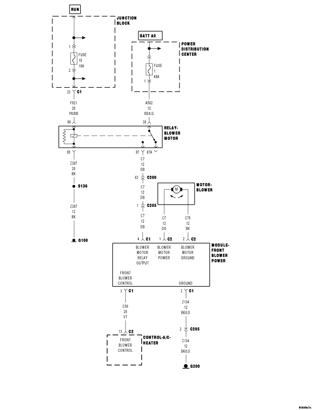
For a complete wiring diagram Refer to Section 8W.
| Possible Causes |
| PDC FUSE #1 OPEN |
| JB FUSE #10 OPEN |
| (C7) BLOWER MOTOR RELAY OUTPUT CIRCUIT SHORTED TO (Z387) GROUND CIRCUIT |
| (A502) FUSED B(+) CIRCUIT SHORTED TO (Z387) GROUND CIRCUIT |
| (C7) BLOWER MOTOR RELAY OUTPUT CIRCUIT SHORTED TO GROUND |
| (A502) FUSED B(+) CIRCUIT SHORTED TO GROUND |
| (F921) FUSED RUN RELAY OUTPUT CIRCUIT SHORTED TO GROUND |
| (Z387) GROUND CIRCUIT OPEN |
| (F921) FUSED RUN RELAY OUTPUT CIRCUIT OPEN |
| (A502) FUSED B(+) CIRCUIT OPEN |
| (C7) BLOWER MOTOR RELAY OUTPUT CIRCUIT OPEN |
| (Z134) GROUND CIRCUIT OPEN |
| (C56) FRONT BLOWER CONTROL CIRCUIT SHORTED TO VOLTAGE |
| (C56) FRONT BLOWER CONTROL CIRCUIT OPEN |
| JUNCTION BLOCK (JB) |
| POWER DISTRIBUTION CENTER (PDC) |
| BLOWER MOTOR RELAY |
| FRONT BLOWER POWER MODULE |
| BLOWER MOTOR |
| A/C HEATER CONTROL |
Diagnostic Test
1. CHECK PDC FUSE #1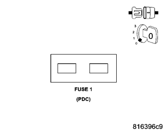
Turn the ignition off.
Remove and inspect PDC Fuse #1.
Is the fuse open?
Yes
- Replace the fuse and Go To 2.
No
- Reinstall the fuse and Go To 7.
2. CHECK BLOWER MOTOR OPERATION
Turn the ignition on.
Turn the blower on and operate it in all speeds.
Does the blower motor operate properly without blowing the fuse?
Yes
- Check the (C7) Blower Motor Relay Output circuit and the (A502) Fused B(+) circuit for a condition causing an intermittent short to ground. Repair as necessary.
- Perform BODY VERIFICATION TEST - VER 1. (Refer to 8 - ELECTRICAL/ELECTRONIC CONTROL MODULES - STANDARD PROCEDURE).
No
- Go To 3
3. CHECK THE (C7) BLOWER MOTOR RELAY OUTPUT CIRCUIT & THE (A502) FUSED B(+) CIRCUIT FOR A SHORT TO THE (Z387) GROUND CIRCUIT
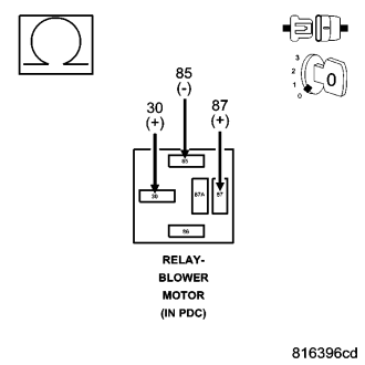
Turn the ignition off.
Remove the Blower Motor Relay from the PDC.
Disconnect the Front Blower Power Module C1 harness connector.
Measure the resistance between the (C7) Blower Motor Relay Output circuit and the (Z387) Ground circuit in the Blower Motor Relay connector.
Measure the resistance between the (A502) Fused B(+) circuit and the (Z387) Ground circuit in the Blower Motor Relay connector.
Is the resistance below 10K ohms on either circuit?
Yes
- Repair all circuits with a resistance below 10k ohms for a short to the (Z387) Ground circuit. Replace PDC Fuse #1.
- Perform BODY VERIFICATION TEST - VER 1. (Refer to 8 - ELECTRICAL/ELECTRONIC CONTROL MODULES - STANDARD PROCEDURE).
No
- Go To 4
4. CHECK THE (C7) BLOWER MOTOR RELAY OUTPUT CIRCUIT & THE (A502) FUSED B(+) CIRCUIT FOR A SHORT TO GROUND
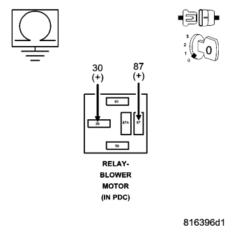
Measure the resistance of the (C7) Blower Motor Relay Output circuit between ground and the Blower Motor Relay connector.
Measure the resistance of the (A502) Fused B(+) circuit between ground and the Blower Motor Relay connector.
Is the resistance below 10K ohms on either circuit?
Yes
- Repair all circuits with a resistance below 10k ohms for a short to ground. Replace PDC Fuse #1.
- Perform BODY VERIFICATION TEST - VER 1. (Refer to 8 - ELECTRICAL/ELECTRONIC CONTROL MODULES - STANDARD PROCEDURE).
No
- Go To 5
5. CHECK BLOWER MOTOR OPERATION WITH A SUBSTITUTE RELAY INSTALLED
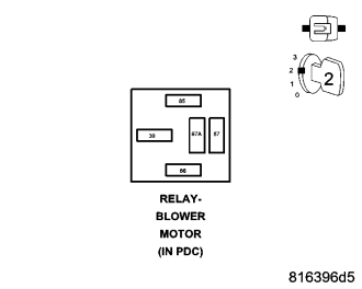
Reconnect the Front Blower Power Module C1 harness connector.
Replace PDC Fuse #1.
Install a substitute relay in place of the existing Blower Motor Relay.
Turn the ignition on.
Turn the blower on and operate it in all speeds.
Does the blower motor operate properly without blowing the fuse?
Yes
- Replace the original Blower Motor Relay in accordance with the Service Information.
- Perform BODY VERIFICATION TEST - VER 1. (Refer to 8 - ELECTRICAL/ELECTRONIC CONTROL MODULES - STANDARD PROCEDURE).
No
- Go To 6
6. CHECK BLOWER MOTOR OPERATION BY BYPASSING THE FRONT BLOWER POWER MODULE
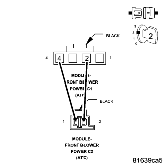
Turn the ignition off.
Disconnect the Front Blower Power Module C1 harness connector.
Disconnect the Front Blower Power Module C2 harness connector.
Connect a jumper wire between the (C7) Blower Motor Relay Output circuit in the Front Blower Power Module C1 harness connector and the (C7) Blower Motor Power circuit in the Front Blower Power Module C2 harness connector.
Connect a jumper wire between the (Z134) Ground circuit in the Front Blower Power Module C1 harness connector and the (C75) Blower Motor Ground circuit in the Front Blower Power Module C2 harness connector.
Replace PDC Fuse #1.
Turn the ignition on.
Does the blower motor run without blowing the fuse?
Yes
- Replace the Front Blower Power Module in accordance with the Service Information. Reinstall the original Blower Motor Relay.
- Perform BODY VERIFICATION TEST - VER 1. (Refer to 8 - ELECTRICAL/ELECTRONIC CONTROL MODULES - STANDARD PROCEDURE).
No
- Replace the Blower Motor in accordance with the Service Information. Replace the fuse and reinstall the original Blower Motor Relay.
- Perform BODY VERIFICATION TEST - VER 1. (Refer to 8 - ELECTRICAL/ELECTRONIC CONTROL MODULES - STANDARD PROCEDURE).
7. CHECK JB FUSE #10
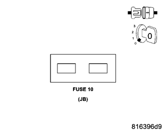
Remove and inspect JB Fuse #10.
Is the fuse open?
Yes
- Using the wiring schematics as a guide, check the (F921) Fused Run Relay Output circuit for a condition causing a short to ground. Repair as necessary.
- Perform BODY VERIFICATION TEST - VER 1. (Refer to 8 - ELECTRICAL/ELECTRONIC CONTROL MODULES - STANDARD PROCEDURE).
No
- Reinstall the fuse and Go To 8.
8. CHECK BLOWER MOTOR OPERATION WITH A SUBSTITUTE RELAY INSTALLED
Install a substitute relay in place of the existing Blower Motor Relay in the PDC.
Turn the ignition on.
Turn the blower on and operate it in all speeds.
Does the blower motor operate properly?
Yes
- Replace the original Blower Motor Relay in accordance with the Service Information.
- Perform BODY VERIFICATION TEST - VER 1. (Refer to 8 - ELECTRICAL/ELECTRONIC CONTROL MODULES - STANDARD PROCEDURE).
No
- Go To 9
9. CHECK THE (Z387) GROUND CIRCUIT FOR AN OPEN
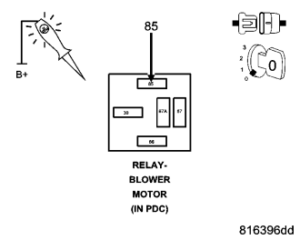
Turn the ignition off.
Remove the substitute Blower Motor Relay.
NOTE: The test light must illuminate brightly. Compare the brightness to that of a direct connection to the battery.
Using a 12-volt test light connected to 12 volts, probe the (Z387) Ground circuit in the Blower Motor Relay connector.
Does the test light illuminate brightly?
Yes
- Go To 10
No
- Repair the (Z387) Ground circuit for an open.
- Perform BODY VERIFICATION TEST - VER 1. (Refer to 8 - ELECTRICAL/ELECTRONIC CONTROL MODULES - STANDARD PROCEDURE).
10. CHECK (F921) FUSED RUN RELAY OUTPUT CIRCUIT FOR AN OPEN
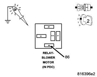
Turn the ignition on.
NOTE: The test light must illuminate brightly. Compare the brightness to that of a direct connection to the battery.
Using a 12-volt test light connected to ground, probe the (F921) Fused Run Relay Output circuit in the Blower Motor Relay connector.
Does the test light illuminate brightly?
Yes
- Go To 11
No
- Repair the (F921) Fused Run Relay Output circuit for an open.
- Perform BODY VERIFICATION TEST - VER 1. (Refer to 8 - ELECTRICAL/ELECTRONIC CONTROL MODULES - STANDARD PROCEDURE).
11. CHECK (A502) FUSED B(+) CIRCUIT FOR AN OPEN
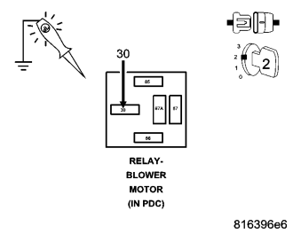
NOTE: The test light must illuminate brightly. Compare the brightness to that of a direct connection to the battery.
Using a 12-volt test light connected to ground, probe the (A502) Fused B(+) circuit in the Blower Motor Relay connector.
Does the test light illuminate brightly?
Yes
- Go To 12
No
- Repair the (A502) Fused B(+) circuit for an open.
- Perform BODY VERIFICATION TEST - VER 1. (Refer to 8 - ELECTRICAL/ELECTRONIC CONTROL MODULES - STANDARD PROCEDURE).
12. CHECK (C7) BLOWER MOTOR RELAY OUTPUT CIRCUIT FOR AN OPEN
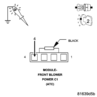
Turn the ignition off.
Install the original Blower Motor Relay.
Disconnect the Front Blower Power Module C1 harness connector.
Turn the ignition on.
NOTE: The test light must illuminate brightly. Compare the brightness to that of a direct connection to the battery.
Using a 12-volt test light connected to ground, back probe the (C7) Blower Motor Relay Output circuit in the Front Blower Power Module C1 harness connector.
Does the test light illuminate brightly?
Yes
- Go To 13
No
- Repair the (C7) Blower Motor Relay Output circuit for an open.
- Perform BODY VERIFICATION TEST - VER 1. (Refer to 8 - ELECTRICAL/ELECTRONIC CONTROL MODULES - STANDARD PROCEDURE).
13. CHECK (Z134) GROUND CIRCUIT FOR AN OPEN
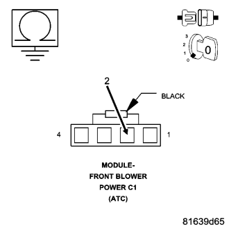
Turn the ignition off.
Measure the resistance of the (Z134) Ground circuit between ground and the Front Blower Power Module C1 harness connector.
Is the resistance below 5.0 ohms?
Yes
- Go To14
No
- Repair the (134) Ground circuit for an open.
- Perform BODY VERIFICATION TEST - VER 1. (Refer to 8 - ELECTRICAL/ELECTRONIC CONTROL MODULES - STANDARD PROCEDURE).
14. CHECK BLOWER MOTOR OPERATION WITH FRONT BLOWER POWER MODULE BYPASSED
Disconnect the Front Blower Power Module C2 harness connector.
Connect a jumper wire between the (C7) Blower Motor Relay Output circuit in the Front Blower Power Module C1 harness connector and the (C7) Blower Motor Power circuit in the Front Blower Power Module C2 harness connector.
Connect a jumper wire between the (Z134) Ground circuit in the Front Blower Power Module C1 harness connector and the (C75) Blower Motor Ground circuit in the Front Blower Power Module C2 harness connector.
Turn the ignition on.
Does the blower motor run at high speed?
Yes
- Go To 15
No
- Replace the Blower Motor in accordance with the Service Information.
- Perform BODY VERIFICATION TEST - VER 1. (Refer to 8 - ELECTRICAL/ELECTRONIC CONTROL MODULES - STANDARD PROCEDURE).
15. CHECK THE (C56) FRONT BLOWER CONTROL CIRCUIT FOR A SHORT TO VOLTAGE
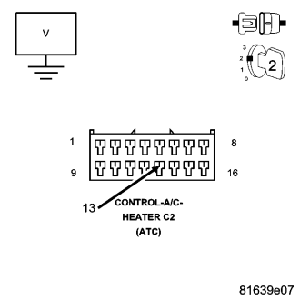
Turn the ignition off.
Disconnect the jumper wires from the Front Blower Power Module C1 and C2 harness connectors.
Disconnect the A/C Heater Control C2 harness connector.
Turn the ignition on.
Measure the voltage of the (C56) Front Blower Control circuit.
Is the voltage above 0.2 volts?
Yes
- Repair the (C56) Front Blower Control circuit for a short to voltage.
- Perform BODY VERIFICATION TEST - VER 1. (Refer to 8 - ELECTRICAL/ELECTRONIC CONTROL MODULES - STANDARD PROCEDURE).
No
- Go To16
16. CHECK THE (C56) FRONT BLOWER CONTROL CIRCUIT FOR AN OPEN
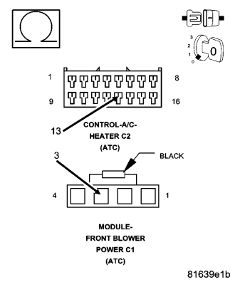
Turn the ignition off.
Measure the resistance of the (C56) Front Blower Control circuit between the Front Blower Power Module C1 harness connector and the A/C Heater Control C2 harness connector.
Is the resistance below 5.0 ohms?
Yes
- Go To17
No
- Repair the (C56) Front Blower Control circuit for an open.
- Perform BODY VERIFICATION TEST - VER 1. (Refer to 8 - ELECTRICAL/ELECTRONIC CONTROL MODULES - STANDARD PROCEDURE).
17. CHECK FRONT BLOWER POWER MODULE OPERATION
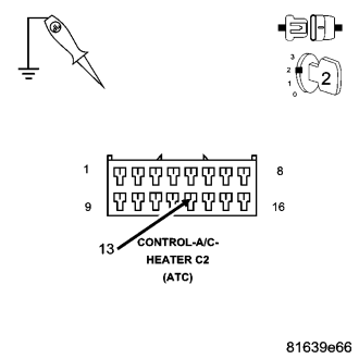
Reconnect the Front Blower Power Module C1 and C2 harness connectors.
Turn the ignition on.
Using a 12-volt test light connected to ground, back probe the (C56) Front Blower Control circuit in the A/C Heater Control C2 harness connector.
Does the blower motor run at high speed?
Yes
- Replace the A/C Heater Control in accordance with the Service Information.
- Perform BODY VERIFICATION TEST - VER 1. (Refer to 8 - ELECTRICAL/ELECTRONIC CONTROL MODULES - STANDARD PROCEDURE).
No
- Replace the Front Blower Power Module in accordance with the Service Information.
- Perform BODY VERIFICATION TEST - VER 1. (Refer to 8 - ELECTRICAL/ELECTRONIC CONTROL MODULES - STANDARD PROCEDURE).