DIAGNOSIS AND TESTING
HEATING AND A/C SYSTEMS
ON-BOARD DIAGNOSTICS
CAUTION: Do not exchange A/C-Heater Controls from vehicle to vehicle. Software versions differ between models and model years. Installing an A/C-Heater Control with software that is incompatible for a given vehicle can result in either improper or failed HVAC system operation.
SETTING FAULTS - ATC AND MTC SYSTEMS
Both the automatic temperature control (ATC) and the manual temperature control (MTC) systems are controlled by the A/C-heater control located on the center bezel of the instrument panel. The ATC system communicates on the controller area network (CAN) B bus and is fully addressable with a scan tool. The MTC system is NOT connected to the CAN bus and is NOT addressable with a scan tool. The A/C-heater control's primary means of fault detection for both heating-A/C systems is through active and stored diagnostic trouble codes (DTCs). The control continuously monitors various internal parameters during normal system operation. If it detects a fault, both an active and a stored diagnostic trouble code (DTC) will set for that parameter. When the offending parameter returns to an acceptable value, the control automatically clears the active DTC. However, the stored DTC remains until cleared (either manually or automatically). Note that DTCs will not set or clear if supply voltage is low.
The A/C-heater control's secondary means of fault detection for both heating-A/C systems is through system tests. For ATC systems, these tests include the HVAC System Test, the Cooldown Test, and Actuator Calibration. For MTC systems, these tests include the HVAC System Test, the Cooldown Test, Actuator Calibration (new MTC installation only), and the Actuator Circuit Test / Door Calibration Function. Refer to System Tests in this Section for a detailed description of each test.
DISPLAYING FAULTS AND READING FAULTS - ATC SYSTEM
Use a scan tool to display DTCs stored in the A/C-heater control of the ATC system (refer to 24 - HVAC - Electrical Diagnostics for more information).
DISPLAYING FAULTS AND READING FAULTS - MTC SYSTEM
Use the A/C-heater control to display DTCs stored in the A/C-heater control of the MTC system. Refer to Entering Display DTC Mode - MTC System; Display Sequencing - MTC System; Reading Diagnostic Trouble Codes - MTC System; Active DTCs - ATC and MTC Systems; Stored DTCs - ATC and MTC Systems; and Clearing Faults - MTC System in this section for additional information.
ENTERING DISPLAY DTC MODE - MTC SYSTEM
To enter the MTC system's Display DTC Mode, perform the following:
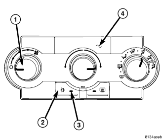
NOTE: An active DTC 33 will prevent the control from entering diagnostic mode and performing certain diagnostic functions. It will also prevent proper A/C mode switch and status indicator function. If this occurs, refer to *A/C HEATER CONTROL WILL NOT ENTER DIAGNOSTIC MODE (MTC) in 24 - HVAC - Electrical Diagnostics for the diagnostic test procedure.
1. Turn the ignition to the On position.
2. Turn the blower motor control (1) to the On position.
3. Press the A/C mode switch (2) down, turn the blower motor control to the Off position, wait until both LEDs illuminate (approximately 5 seconds) and then release the A/C switch. If there are active or stored DTCs to display, the A/C status indicator (3) will begin to flash. If there are no active or stored DTCs to display, the LEDs on the A/C-heater control (4) will turn off and the system will automatically exit the mode of operation.
4. To manually exit Display DTC Mode, either turn the ignition off or disconnect the negative battery cable from the battery.
DISPLAY SEQUENCING - MTC SYSTEM
MTC system DTCs will display in ascending numerical order but not in chronological order. Active DTCs will display before stored DTCs. If there are active and stored DTCs for the same parameter, the A/C-heater control will NOT display the stored DTC for that parameter. The EBL status indicator will illuminate and remain illuminated while the A/C-heater control is displaying stored DTCs. After displaying all active and stored DTCs, the A/C-heater control restarts at the beginning, displaying all DTCs again. To restart the sequence from the beginning while the A/C-heater control is displaying DTCs, press the EBL mode switch down, and then release it. This will cause the A/C-heater control to quit displaying the present code, turn off all LEDs for 2.0 seconds, and then it will begin flashing all DTCs again from the beginning.
READING DIAGNOSTIC TROUBLE CODES - MTC SYSTEM
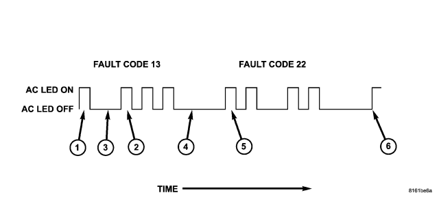
All active and stored DTCs for the MTC system have an assigned code number. The A/C status indicator flashes in a series of pulses to display the code numbers. Each pulse has an indicator on time of 0.5 seconds. The tens unit value (1) is flashed first followed by the ones unit value (2). A 2.0 second indicator off-time (3) separates the unit values. When displaying multiple DTCs, the A/C status indicator will go off for five seconds (4) before displaying the next DTC (5). After displaying all DTCs (6), the sequence will repeat until exiting Display DTC Mode.
ACTIVE DTCs - ATC AND MTC SYSTEMS
Refer to 24 - HVAC - Electrical Diagnostics to diagnose HVAC system DTCs.
STORED DTCs - ATC AND MTC SYSTEMS
The HVAC System Test, found in 24 - HVAC - Electrical Diagnostics, provides a means for diagnosing stored DTCs. The HVAC System Test consists of multiple diagnostic procedures which cover:
- A/C System Performance
- System Controls
- Air-door Functionality
Either perform the entire diagnostic procedure for a complete system test or perform an individual procedure if diagnosing a specific symptom, condition, or DTC.
CLEARING FAULTS - ATC SYSTEM
For every fault that sets, the A/C-heater control maintains an independent count of the number of key cycles since the active DTC cleared, the odometer reading when the DTC set, and the elapsed ignition on time that the DTC was active. When the number of key cycles (by parameter) reaches a global number, the system automatically clears all of the information associated with that DTC. A loss of battery voltage will also clear all active DTCs and associated data from memory. However, upon reconnecting the battery and activating the A/C-heater control ("Ignition" line going "HIGH"), the system will again evaluate all parameters and will set active DTCs for parameters outside of acceptable limits.
DTCs can also be cleared manually from the A/C-heater control (which also resets key cycle counters). Use a scan tool to clear DTCs stored in the A/C-heater control of the ATC system (refer to 24 - HVAC - Electrical Diagnostics for more information).
CLEARING FAULTS - MTC SYSTEM
To clear DTCs stored in the A/C-heater control of the MTC system, perform the following:
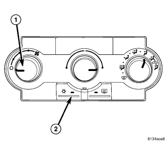
NOTE: An active DTC 33 will prevent the control from entering diagnostic mode and performing certain diagnostic functions. It will also prevent proper A/C mode switch and status indicator function. If this occurs, refer to *A/C HEATER CONTROL WILL NOT ENTER DIAGNOSTIC MODE (MTC) in 24 - HVAC - Electrical Diagnostics for the diagnostic test procedure.
NOTE: An active DTC 34 will prevent the control from performing certain diagnostic functions and it will prevent proper EBL mode switch and status indicator function. If active, diagnose and repair DTC 34 before proceeding. Refer to 24 - HVAC - Electrical Diagnostics for the diagnostic test procedure.
1. Turn the ignition to the On position.
2. Turn the blower motor control (1) to the On position.
3. Press the A/C mode switch (2) down, turn the blower motor control to the Off position, wait until both LEDs illuminate (approximately 5 seconds) and then release the A/C mode switch.
4. When the A/C status indicator begins flashing DTCs, set the Mode switch to the floor position, simultaneously press the A/C mode switch and the EBL mode switch down until both LEDs start flashing (approximately 5 seconds) and then release the mode switches. Stored DTCs will clear from memory in approximately two seconds.
SYSTEM TESTS
HVAC SYSTEM TEST - ATC AND MTC SYSTEMS
The HVAC System Test, found in 24 - HVAC - Electrical Diagnostics, provides a starting point in the diagnostic process by identifying the appropriate diagnostic procedure or system test to perform when diagnosing a given symptom, condition, or DTC. It also provides a means for testing the entire HVAC system by utilizing the A/C-heater control's On-Board System Tests. The On-Board System Tests can also assist in diagnosing stored DTCs.
ACTUATOR CALIBRATION - ATC SYSTEM
The Actuator Calibration function homes and repositions the air-door actuators, removes accumulated positioning errors, and checks for air-door span faults. Once actuated, the entire process takes approximately 90 seconds. Upon completion, all air-door actuators should return to the position that the system is currently requesting. Running the Actuator Calibration function is the only way to detect air-door travel too large faults and air-door travel too small faults. These faults, if present, will display on the scan tool after running the Actuator Calibration function.
STARTING ACTUATOR CALIBRATION - ATC SYSTEM
Use a scan tool to start the Actuator Calibration function.
ACTUATOR CALIBRATION - MTC SYSTEM
NOTE: Diagnose and repair Actuator Circuit Test faults (DTC 61, 62, 63, 64, 65, 66, 67, 68, 69, 71, and 72) before diagnosing Overcurrent faults (DTC 41, 42, 43, and 44) and Calibration faults (DTC 18, 21, 22, 23, 24, 25, 45, 46, 47, 48, 51, 52, 53, 54, 55, and 56). Diagnose and repair Overcurrent faults (DTC 41, 42, 43, and 44) before diagnosing Calibration faults (DTC 18, 21, 22, 23, 24, 25, 45, 46, 47, 48, 51, 52, 53, 54, 55, and 56).
The A/C-Heater Control automatically runs the Actuator Calibration function upon ignition on after installing a new A/C-Heater Control. The Actuator Calibration function homes and repositions the air-door actuators, removes accumulated positioning errors, and checks for air-door span faults. Once actuated, the entire process takes approximately 90 seconds. Upon completion, all air-door actuators should return to the position that the system is currently requesting. Running the Actuator Calibration function is the only way to detect air-door travel too large faults, air-door travel too small faults, air-door bound faults, and air-door broken linkage faults. These faults, if present, will display when checking for DTCs in the A/C-heater control.
STARTING ACTUATOR CALIBRATION MANUALLY - MTC SYSTEM
Refer to Starting The Actuator Circuit Test / Door Calibration Function - MTC System in this section.
ACTUATOR CIRCUIT TEST / DOOR CALIBRATION FUNCTION - MTC SYSTEM
NOTE: Diagnose and repair Actuator Circuit Test faults (DTC 61, 62, 63, 64, 65, 66, 67, 68, 69, 71, and 72) before diagnosing Overcurrent faults (DTC 41, 42, 43, and 44) and Calibration faults (DTC 18, 21, 22, 23, 24, 25, 45, 46, 47, 48, 51, 52, 53, 54, 55, and 56). Diagnose and repair Overcurrent faults (DTC 41, 42, 43, and 44) before diagnosing Calibration faults (DTC 18, 21, 22, 23, 24, 25, 45, 46, 47, 48, 51, 52, 53, 54, 55, and 56).
The Actuator Circuit Test / Door Calibration function first tests the air-door electrical circuits for shorts and then it homes and repositions the air-doors to remove accumulated positioning errors and to check for air-door span faults. This test / function supplements the continuous actuator drive system diagnostics and can provide greater detail about shorted air-door electrical circuits by identifying up to three door driver circuits shorted simultaneously. This test will also detect air-door travel too large faults, air-door travel too small faults, air-door bound faults, and air-door broken linkage faults. The Actuator Circuit Test / Door Calibration function must be manually actuated. Faults detected will display when checking for DTCs in the A/C-heater control.
STARTING THE ACTUATOR CIRCUIT TEST / DOOR CALIBRATION FUNCTION - MTC SYSTEM
NOTE: By running the Actuator Circuit Test / Door Calibration Function, the A/C-Heater Control can identify up to three door driver circuits shorted simultaneously. A DTC 72 will set if more than three door driver circuits are shorted in the same direction (e.g. four door driver circuits all shorted to ground) or if two or more door driver circuits are shorted with at least one door driver circuit shorted to ignition and one door driver circuit shorted to ground. To ensure a proper diagnosis, diagnose and repair Actuator Circuit Test faults in the following order: If present, diagnose and repair DTC 72 first, then DTC 62, then DTC 61, then DTCs 64, 66, 68, or 71, and finally DTCs 63, 65, 67, or 69. In addition, always test the door driver circuits after each repair by clearing DTCs, and then running the Actuator Circuit Test / Door Calibration Function, and then checking for DTCs.
To start the Actuator Circuit Test / Door Calibration function for the MTC system, perform the following:
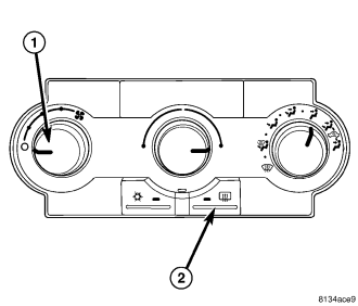
NOTE: An active DTC 34 will prevent the control from performing certain diagnostic functions and it will prevent proper EBL mode switch and status indicator function. If this occurs, diagnose and repair DTC 34 before running the Actuator Circuit Test / Door Calibration function. Refer to 24 - HVAC - Electrical Diagnostics for the diagnostic test procedure.
1. Turn the ignition to the On position.
2. Turn the blower motor control (1) to the Off position.
3. Press and hold the EBL mode switch (2) down and then turn the blower motor control on. Continue to hold the EBL mode switch down until the EBL status indicator begins flashing. Then, release the mode switch. While the test / function is running, the EBL status indicator will flash once per second. If the test / function passes, the EBL status indicator will stop flashing. However, if the test / function fails, the A/C and EBL status indicators will flash alternately. Faults detected will display when checking for DTCs in the A/C-heater control.
COOLDOWN TEST - ATC AND MTC SYSTEMS
The Cooldown Test checks A/C system performance by measuring the system's ability to lower the evaporator temperature 11.11° C (20° F) as measured by the evaporator temperature sensor. The following are prerequisites of the Cooldown Test. Verify each of the following before running the Cooldown Test:
- For the ATC system, the Cooldown Test will NOT start if DTC B1031 or B1032 is active. If active, diagnose and repair either DTC before proceeding (Refer to 24 - HVAC - Electrical Diagnostics for a complete list of HVAC related symptoms).
- For the MTC system, the Cooldown Test will NOT start if DTC 31 or 32 is active. If active, diagnose and repair either DTC before proceeding (Refer to 24 - HVAC - Electrical Diagnostics for a complete list of HVAC related symptoms).
- For both systems, verify that the refrigerant system has an adequate charge. Check and repair as necessary before proceeding (refer to 24 - HEATING & AIR CONDITIONING/PLUMBING - DIAGNOSIS AND TESTING - REFRIGERANT SYSTEM LEAKS).
- For both systems, verify that the blower motor operates correctly in all speeds. Diagnose and repair all blower motor related faults before proceeding.
- For both systems, verify that the ambient temperature of the work area is above 18.3° C (65° F) before proceeding. Move the vehicle to a warmer work area if necessary.
- For both systems, verify that the evaporator temperature is above 18.3° C (65° F) before proceeding.
- For both systems, verify that the A/C compressor is NOT running. If the A/C compressor is running, turn the A/C off and allow the evaporator to warm up before proceeding.
STARTING THE COOLDOWN TEST - ATC SYSTEM
Once all of the prerequisites have been met, the Cooldown Test for the ATC system can be actuated by sending a command with a scan tool. Once started, the ATC A/C-heater control automatically sets the blower speed and positions the air-doors for optimal A/C performance. It also sends a request for A/C operation on the CAN B bus. The Cooldown Test can take up to two minutes to run and, will stop running if any of the following occurs:
- The ignition is turned off.
- The A/C compressor is requested off.
- DTC B1031 or B1032 sets during the Cooldown Test.
While the Cooldown Test is running, the A/C status indicator will flash. During this time the A/C-heater control will ignore most of its inputs. If the ATC system passes the test, the A/C status indicator will stop flashing. However, if the ATC system fails the test, both the A/C and EBL status indicators will flash alternately and an active DTC B10B2 will set. The status indicators will continue to flash until either a successful Cooldown Test is executed or until the vehicle is driven a specified number of miles or after 5 ignition cycles. In addition, DTC B10B2 will remain active until a successful Cooldown Test is executed. Always check for DTCs in the A/C-heater control after running the Cooldown Test.
STARTING THE COOLDOWN TEST - MTC SYSTEM
Once all of the prerequisites have been met, the Cooldown Test for the MTC system can be actuated by performing the following:
NOTE: An active DTC 33 will prevent the control from entering diagnostic mode and performing certain diagnostic functions. It will also prevent proper A/C mode switch and status indicator function. If this occurs, refer to *A/C HEATER CONTROL WILL NOT ENTER DIAGNOSTIC MODE (MTC) in 24 - HVAC - Electrical Diagnostics for the diagnostic test procedure.
1. Verify that the ignition is in the Off position.
2. Turn the blower motor control (1) to the Off position.
3. Start the engine.
4. Press and hold the A/C mode switch (2) down and then turn the blower motor control to high speed. Continue to hold the A/C mode switch down until the A/C status indicator begins flashing, Then, release the mode switch.
Once actuated, the MTC A/C-heater control automatically positions the air-doors for optimal A/C performance and sends a request for A/C operation to the cluster (CCN) via hardwired circuits. The Cooldown Test can take up to two minutes to run. The test will stop running if any of the following occurs:
- The ignition is turned to the Off position.
- The blower motor control is turned to the any position other than high speed.
- DTC 83 or 84 sets during the Cooldown Test.
While the Cooldown Test is running, the A/C status indicator will flash. During this time the A/C-heater control will ignore most of its inputs. If the MTC system passes the test, the A/C status indicator will stop flashing. However, if the MTC system fails the test, both the A/C and EBL status indicators will flash alternately and an active DTC 35 will set. The status indicators will continue to flash until either a successful Cooldown Test is executed or until the vehicle's ignition on time has exceeded a specified value. In addition, DTC 35 will remain active until a successful Cooldown Test is executed. Always check for and diagnose DTCs present in the A/C-heater control after running the Cooldown Test. If the Cooldown Test fails, service the heating-A/C system as required.
A/C PERFORMANCE
The A/C system is designed to provide the passenger compartment with low temperature and low humidity air. The A/C evaporator, located in the HVAC housing is cooled to temperatures near the freezing point. As warm damp air passes over the fins of the A/C evaporator, the air transfers its heat to the refrigerant in the evaporator coils and the moisture in the air condenses on the evaporator fins. During periods of high heat and humidity, an A/C system will be more effective in the Recirculation mode (max-A/C). With the system in the Recirculation mode, only air from the passenger compartment passes through the A/C evaporator. As the passenger compartment air dehumidifies, the A/C system performance levels rise.
Humidity has an important bearing on the temperature of the air delivered to the interior of the vehicle. It is important to understand the effect that humidity has on the performance of the A/C system. When humidity is high, the A/C evaporator has to perform a double duty. It must lower the air temperature, and it must lower the temperature of the moisture in the air that condenses on the evaporator fins. Condensing the moisture in the air transfers heat energy into the evaporator fins and coils. This reduces the amount of heat the A/C evaporator can absorb from the air. High humidity greatly reduces the ability of the A/C evaporator to lower the temperature of the air.
However, evaporator capacity used to reduce the amount of moisture in the air is not wasted. Wringing some of the moisture out of the air entering the vehicle adds to the comfort of the passengers. Although, an owner may expect too much from their A/C system on humid days. A performance test is the best way to determine whether the system is performing up to design standards. This test also provides valuable clues as to the possible cause of trouble with the A/C system. The ambient air temperature in the location where the vehicle will be tested must be a minimum of 21° C (70° F) for this test.
A/C PERFORMANCE TEST
WARNING: Refer to the applicable warnings and cautions for this system before performing the following operation (refer to 24 - HEATING & AIR CONDITIONING/PLUMBING - WARNING) and (refer to 24 - HEATING & AIR CONDITIONING/PLUMBING - CAUTION). Failure to follow the warnings and cautions could result in possible personal injury or death.
NOTE: When connecting the service equipment coupling to the line fitting, verify that the valve of the coupling is fully closed. This will reduce the amount of effort required to make the connection.
NOTE: The work area ambient temperature and the evaporator temperature must be above 18.3°C (65°F) prior to conducting the A/C Performance Test.
1. Conduct the A/C System Performance Test (Cooldown Test) found within the HVAC System Test (refer to 24 - HVAC Electrical Diagnostics). If no diagnostic trouble codes (DTCs) are found in the A/C-heater control or the powertrain control module (PCM) or engine control module (ECM), depending on engine application, go to STEP 2. If any DTCs are found, repair as required, then proceed to STEP 2.
2. Connect a tachometer and a manifold gauge set.
3. Operate the heating-A/C system under the following conditions.
- Engine at 1,000 rpm at operating temperature
- Doors and windows closed
- Transmission in Park
- A/C-heater controls set to Recirculation mode (max-A/C), full cool, panel mode, high blower and with A/C compressor engaged. If the A/C compressor does not engage, see the A/C System Diagnosis chart.
4. Insert a thermometer in the driver side center panel air outlet and operate the A/C system until the thermometer temperature stabilizes.
5. With the A/C compressor clutch engaged, compare the air temperature at the center panel outlet and the A/C compressor discharge pressure (high side) to the A/C Performance Temperature and Pressure chart. The compressor clutch may cycle, depending upon the ambient temperature and humidity. If the clutch cycles, use the readings obtained before the clutch disengaged.
| Ambient Air Temperature | 21°C (70°F) | 27°C (80°F) | 32°C (90°F) | 38°C (100°F) | 43°C (110°F) |
| Maximum Allowable Air Temperature at Center Panel Outlet | 9°C (48°F) | 9°C (48°F) | 12°C (54°F) | 15°C (59°F) | 18°C (65°F) |
| Suction Pressure at Service Port (Low Side) | 138 to 207 kPa (20 to 30 psi) | 138 to 207 kPa (20 to 30 psi) | 207 to 276 kPa (30 to 40 psi) | 207 to 276 kPa (30 to 40 psi) | 241 to 310 kPa (35 to 45 psi) |
| Discharge Pressure at Service Port (High Side) | 1034 to 1724 kPa (150 to 250 psi) | 1379 to 2068 kPa (200 to 300 psi) | 1551 to 2241 kPa (225 to 325 psi) | 1724 to 2413 kPa (250 to 350 psi) | 2068 to 2758 kPa (300 to 400 psi) |
6. If the air outlet temperature fails to meet the specifications in the A/C Performance Temperature and Pressure chart, or if the A/C compressor discharge pressure is high, refer to the A/C System Diagnosis chart.
| Condition | Possible Causes | Correction |
| Rapid A/C compressor clutch cycling (ten or more cycles per minute). | Very low refrigerant system charge. | See Refrigerant System Leaks in this group. Test the refrigerant system for leaks. Repair, evacuate and charge the refrigerant system, if required. |
| Equal pressures, but the compressor clutch does not engage. | 1. No refrigerant in the refrigerant system. | 1. See Refrigerant System Leaks in this group. Test the refrigerant system for leaks. Repair, evacuate and charge the refrigerant system, if required. |
2. Open fuse. | 2. Check the fuses in the Power distribution block and junction block. Repair the shorted circuit or component and replace the fuses, if required. Refer to Group 8. | |
3. Inoperative A/C compressor clutch coil. | 3. See A/C Compressor Clutch Coil in this group. Test the compressor clutch coil and replace, if required. | |
4. Inoperative A/C compressor clutch relay. | 4. See A/C Compressor Clutch Relay in this group. Test the compressor clutch relay and relay circuits. Repair the circuits or replace the relay, if required. | |
5. Improperly installed or inoperative evaporator temperature sensor. | 5. See Evaporator Temperature Sensor in this group. Test the sensor and replace, if required. | |
6. Inoperative A/C pressure transducer. | 6. See A/C Pressure Transducer in this group. Test the sensor and replace, if required. | |
7. Inoperative Powertrain Control Module (PCM) or Engine Control Module (ECM). | 7. Refer to Group 9 - Engine Electrical Diagnostics for testing of the PCM/ECM. Test the PCM/ECM and replace, if required. | |
| Normal pressures, but A/C Performance Test air temperatures at center panel outlet are too high. | 1. Excessive refrigerant oil in system. | 1. See Refrigerant Oil Level in this group. Recover the refrigerant from the refrigerant system and inspect the refrigerant oil content. Restore the refrigerant oil to the proper level, if required. |
2. Blend door actuator (s) improperly installed or inoperative. | 2. See Blend Door Actuator in this group. Inspect the actuator(s) for proper operation and replace, if required. | |
3. Blend-air door(s) inoperative or sealing improperly. | 3. See HVAC Housing in this group. Inspect the blend-air door(s) for proper operation and sealing. Repair if required. | |
| The low side pressure is normal or slightly low, and the high side pressure is too low. | 1. Low refrigerant system charge. | 1. See Refrigerant System Leaks in this group. Test the refrigerant system for leaks. Repair, evacuate and charge the refrigerant system, if required. |
2. Refrigerant flow through the A/C evaporator is restricted. | 2. See A/C Evaporator in this group. Replace the restricted A/C evaporator, if required. | |
3. Inoperative A/C compressor. | 3. See A/C Compressor in this group. Replace the A/C compressor, if required. | |
| The low side pressure is normal or slightly high, and the high side pressure is too high. | 1. A/C condenser air flow restricted. | 1. Check the A/C condenser for damaged fins, foreign objects obstructing air flow through the condenser fins, and missing or improperly installed air seals. Clean, repair, or replace components as required. |
2. Refrigerant flow through the A/C receiver/drier is restricted. | 2. See A/C Receiver/Drier in this group. Replace the restricted receiver/drier, if required. | |
3. Inoperative radiator cooling fan. | 3. Test the radiator cooling fan and replace, if required. Refer to Group 7 - Cooling. | |
4. Refrigerant system overcharged. | 4. See Refrigerant System Charge in this group. Recover the refrigerant from the refrigerant system. Charge the refrigerant system to the proper level, if required. | |
5. Air in the refrigerant system. | 5. See Refrigerant System Leaks in this group. Test the refrigerant system for leaks. Repair, evacuate and charge the refrigerant system, if required. | |
6. Engine overheating. | 6. Test the engine cooling system and repair, if required. Refer to Group 7 - Cooling. | |
| The low side pressure is too high, and the high side pressure is too low. | 1. Accessory drive belt slipping. | 1. Inspect the accessory drive belt condition and tension. Repair as required. Refer to Group 7 - Cooling. |
2. Inoperative A/C expansion valve. | 2. See A/C Expansion Valve in this group. Replace the valve, if required. | |
3. Inoperative A/C compressor. | 3. See A/C Compressor in this group. Replace the A/C compressor, if required. | |
| The low side pressure is too low, and the high side pressure is too high. | 1. Restricted refrigerant flow through the refrigerant lines. | 1. See Liquid Line, Suction Line and Discharge Line in this group. Inspect the refrigerant lines for kinks, tight bends or improper routing. Correct the routing or replace the refrigerant line, if required. |
2. Restricted refrigerant flow through the A/C expansion valve. | 2. See A/C Expansion Valve in this group. Replace the valve, if required. | |
3. Restricted refrigerant flow through the A/C condenser. | 3. See A/C Condenser in this group. Replace the restricted A/C condenser, if required. |
HEATER PERFORMANCE
Before performing the following tests, refer to Group 7 - Cooling for the procedures to check the engine coolant level and flow, engine coolant reserve/recovery system operation, accessory drive belt condition and tension, radiator air flow and the fan drive operation. Perform the A/C System Performance Test, which is found within the HVAC System Test (refer to 24 - HVAC Electrical Diagnostics). If any diagnostic trouble codes (DTCs) are found in the A/C-heater control or the powertrain control module (PCM), repair as necessary.
MAXIMUM HEATER OUTPUT
Engine coolant is delivered to the heater core through two heater hoses. With the engine idling at normal operating temperature, set the temperature control to the full hot position, the mode control to the floor position, and the blower motor control to the highest speed position. Using a test thermometer, check the temperature of the air being discharged at the front floor outlets. Compare the test thermometer reading to the Heater Temperature Reference chart.
| Ambient Air Temperature |
16° C (60° F) |
21° C (70° F) |
27° C (80° F) |
32° C (90° F) |
| Minimum Heater System Air Outlet Temperature |
52° C (125° F) |
56° C (133° F) |
59° C (139° F) |
62° C (144° F) |
If the heater outlet air temperature is below the minimum specification, refer to Group 7 - Cooling. Both of the heater hoses should be hot to the touch. The coolant return heater hose should be slightly cooler than the coolant supply heater hose. If the return hose is much cooler than the supply hose, locate and repair the engine coolant flow obstruction in the cooling system (refer to Group 7 - Cooling for more information).
OBSTRUCTED COOLANT FLOW
Possible locations or causes of obstructed coolant flow are as follows:
- Inoperative water pump.
- Inoperative thermostat.
- Pinched or kinked heater hoses.
- Improper heater hose routing.
- Plugged heater hoses or supply and return ports at the cooling system connections.
- Plugged heater core.
If proper coolant flow through the cooling system is verified, and heater outlet air temperature is low, a mechanical problem may exist.
MECHANICAL PROBLEMS
Possible locations or causes of insufficient heat due to mechanical problems are as follows:
- Obstructed cowl air intake.
- Obstructed heater system outlets.
- Inoperative engine thermostat.
- Inoperative blower motor system.
- Inoperative A/C-heater control.
- Inoperative blend door actuator(s).
- Inoperative, obstructed or improperly installed blend-air door.
TEMPERATURE CONTROL
If the heater outlet air temperature cannot be adjusted with the temperature control on the A/C-heater control, the following could require service:
- Inoperative A/C-heater control.
- Inoperative blend door actuator(s).
- Inoperative, obstructed or improperly installed blend-air door.
- Improper engine coolant temperature.
- Inoperative related wiring harness or connectors.