ASSEMBLY-INSTRUMENT PANEL
REMOVAL
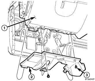
1. Before proceeding with the following repair procedure, review all warnings and cautions. (Refer to 23 - BODY/INSTRUMENT PANEL - WARNING)
2. Disconnect and isolate battery negative cable.
3. Remove the bolts (3) and remove the drivers side hush panel (2).
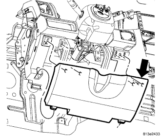
4. Using a trim stick C-4755 or equivalent, separate the upper clips and rotate the cover down and release the lower hinges at the bottom and remove the opening cover.
WARNING: Before servicing the steering column the airbag system must be disarmed. Failure to do so may result in accidental deployment of the airbag and possible personal injury. (refer to 8 - electrical/restraints/driver airbag - removal).
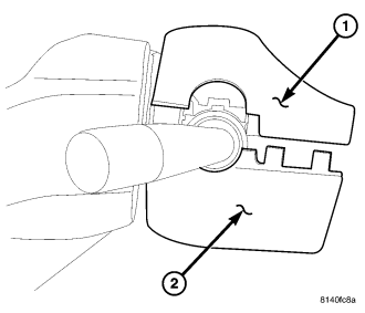
5. Remove the three bolts in the lower shroud (2).
NOTE: Use care not to break off the tangs on the shrouds.
6. Then unsnap the lower shroud (2) from the upper shroud (1).
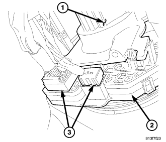
7. Disconnect the steering column electrical connectors (3).
CAUTION: Do not turn the steering wheel more than 90° or damage to the clockspring may occur.
8. Position front wheels straight ahead.
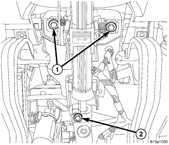
9. Remove the pinch bolt (2).
10. Remove the column support bolts (1).
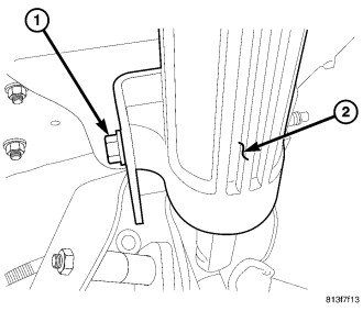
11. Remove the column cross bolt (1) and slide the column (2) downward off the bracket and remove the steering column.
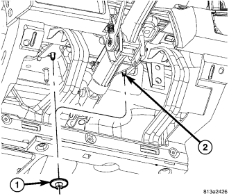
12. Remove the nuts (1) attaching the instrument panel to the pedal support bracket.
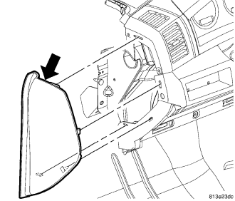
13. Separate the door seal as necessary to access the side covers.
14. Using a trim stick C-4755 or equivalent, remove the left side cover.
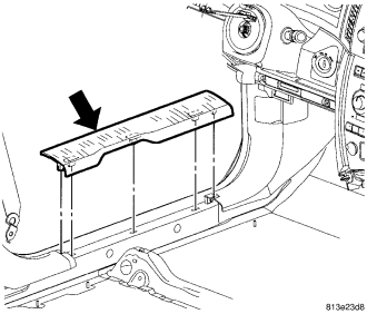
15. Remove the left side door sill trim.
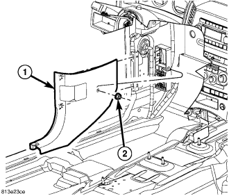
16. Remove the drivers side cowl trim panel.
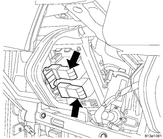
17. Disconnect the electrical connectors.
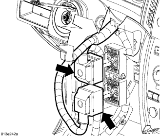
18. Disconnect the electrical connectors.
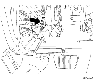
19. Remove the bolts and disconnect the ground wires within the steering column opening to the left of the steering column.
20. Disconnect the white adjustable pedal electrical connector.
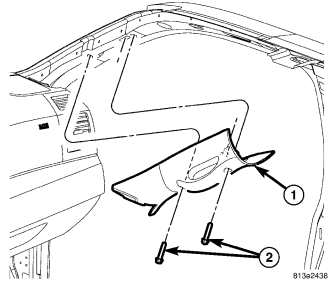
21. Remove the bolts (2) and remove the left a-pillar trim. * Right side shown, left side similar.
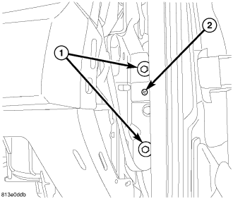
22. Remove the two left side bolts and one screw at the a-pillar support. * Right side shown, left side similar.
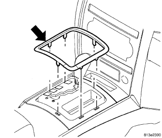
23. Using a trim stick C-4755 or equivalent, remove the shifter bezel ring.
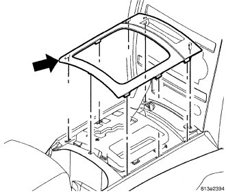
24. Using a trim stick C-4755 or equivalent, remove the shifter bezel.
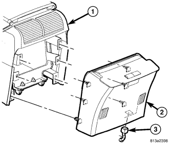
25. Remove the center console back cover (2) and disconnect the electrical connector (3).
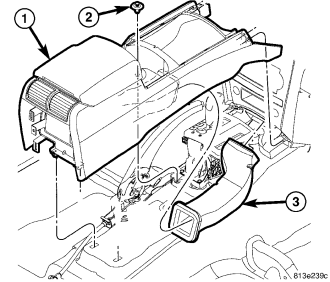
26. Remove the screws (2) and remove the console (1).
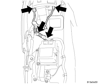
27. Disconnect the electrical connectors under the console.
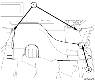
28. Disconnect the stabilizer from the outer panel of the box compartment.
29. Open the glove box and push the stop tabs down to drop the glove box out of the instrument panel.
30. Rotate the box down and release the door hinges (2) at the bottom and remove the glove box.
31. Remove the passenger side hush panel.
32. Remove the right side door sill trim. * Left side door sill trim shown, right side similar.
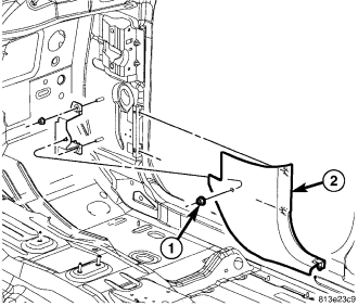
33. Remove the nut (1), separate the right cowl trim panel and remove.
34. Remove the right side end cap. * Left side end cap shown, right side similar.
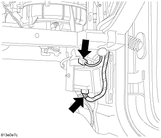
35. Disconnect the electrical connectors.
36. Remove the bolts and remove the right a-pillar trim panel.
37. Remove the two right side bolts and one screw at the a-pillar support.
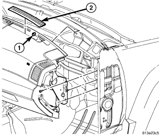
38. Using a trim stick C-4755 or equivalent, remove the defroster grilles (2).
39. Remove the two fenceline nuts (1).
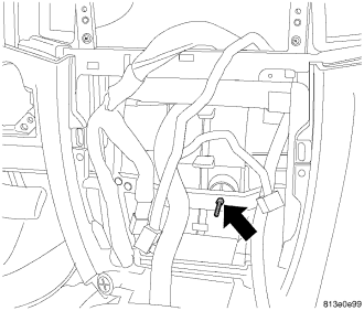
40. Using a trim stick C-4755 or equivalent, remove the radio bezel.
41. Remove the screw inside the lower storage bin, if equipped.
42. Using a trim stick C-4755 or equivalent, remove the center bezel and disconnect the electrical connectors.
43. Remove the nut from the HVAC support stud behind the center bezel.
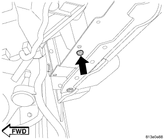
44. Remove the screw to the HVAC from under the glove box opening.
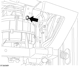
45. Remove the HVAC bracket bolt from the glove box opening.
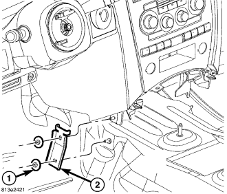
46. Remove the left and right center support brackets. * Left side shown, right side similar.
47. Remove the center floor duct (3).
48. Remove the radio.
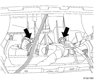
49. Remove the two HVAC bolts from the radio opening.
50. Remove the instrument panel assembly.
INSTALLATION
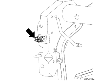
1. Before proceeding with installation of the instrument panel assembly, remove the load clips from each a-pillar and install onto the sides of the panel using the screw.
2. Place the instrument panel into the vehicle and position onto the a-pillars using the load clips (2).
3. Install the two bolts on the right side and tighten the bolts to 11 N·m (95 in. lbs.).
4. Install the two fenceline nuts (1).
5. Guide the peddle support studs (2) on the drivers side, into the slots in the instrument panel reinforcement.
6. Position the center stack brackets (2) in front of the duct work.
7. Position the instrument panel back and guide the HVAC stud.
8. Continue to rotate the instrument panel back and guide the tube brackets located in the radio opening, into the HVAC.
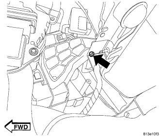
9. Install the screw at the bottom of the column opening next to the center stack up from the bottom attaching the HVAC.
10. Install the bolt at the HVAC blower motor housing.
11. Install the screw at the bottom of the glove box opening to the blower motor housing support.
12. Snap the lower glove box hinges (2) over the pivots (1) and rotate up.
13. Push the stop tabs down and close the glove box.
14. Connect the stabilizer to the outer side of the box compartment.
15. Connect the right side wiring.
16. Install the right hush panel trim.
17. Install the right cowl trim and position the door seal back.
18. Position the right side door sill trim and seat fully. * Left side shown, right side similar.
19. Install the right a-pillar trim, the bolts and position the door seal back.
20. Install the two bolts on the left side and tighten to 11 N·m (95 in. lbs.). * Right side shown, left side similar.
21. Position the right side end cap and seat fully. * Left side shown, right side similar.
22. Install the two nuts (1) on the studs (2) above the column tighten the nuts to 12 N·m (105 in. lbs.).
23. Connect the two left bulk connectors.
24. Connect the two fuse block connectors.
25. Connect the white connector to adjustable brake pedal.
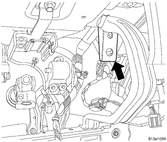
26. Install the grounds within the steering column opening and install the bolts.
27. Install the left cowl trim panel (1) and install the nut (2).
28. Install the left door sill.
CAUTION: Do not turn the steering wheel more than 90° or damage to the clockspring may occur.
29. Install the column cross bolt (1) and tighten to 12 N·m (105 in. lbs.).
30. Position the steering column shaft into the slip joint.
31. Lift the column into position and install the bolts (1).
32. Tighten the bolts to 12 N·m (105 in. lbs.).
33. Slide the coupler onto the column shaft and install a new coupler bolt (2). Tighten the coupler bolt to 49 N·m (36 ft. lbs.).
34. Connect the electrical connector (3) for the multi-function switch (2).
35. Install the upper shroud (1) on the column.
36. Install the lower shroud (2) to the column.
37. Snap the two halves back into place.
38. Install the three mounting bolts to secure the shroud in place.
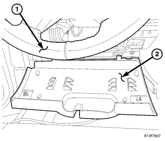
39. Snap the steering column opening cover (2) lower hinges onto the pins and roll cover up.
40. Seat the upper retaining clips fully.
41. Install the hush panel.
42. Connect the column electrical connectors.
43. Install the column covers.
44. Install the left a-pillar trim, the bolts and position the door seal back. * Right a-piller trim shown, left similar.
45. Position the left side end cap and seat fully.
46. Install the center support nut onto the stud.
47. Install the two HVAC bolts within the radio opening.
48. Install the radio.
49. Install the radio bezel.
50. Install the left and right center support brackets and nuts and tighten to 12 N·m (105 in. lbs.). * Left side shown, right side similar.
51. Position the center wire harness and connect the electrical connectors.
52. Install the center bezel.
53. Install the screw inside the lower storage bin, if equipped.
54. Position the defroster vents (2) and seat fully.
55. Connect the center harness electrical connectors (ground, module, shifter, brake lever).
56. Install the center floor duct (3).
57. Position the console (1) into the vehicle and install the screws (2).
58. Connect the electrical connector (3) and install the rear cover (2) onto the console (1).
59. Position the shifter bezel and seat fully.
60. Position the shifter bezel trim ring and seat fully.