OPERATION
3.7L GAS/3.0L DIESEL VEHICLES
The transmission control module (TCM) determines the current operating conditions of the vehicle and controls the shifting process for shift comfort and driving situations. It receives this operating data from sensors and broadcast messages from other modules.
The TCM uses inputs from several sensors that are directly hardwired to the controller and it uses several indirect inputs that are used to control shifts. This information is used to actuate the proper solenoids in the valve body to achieve the desired gear.
The shift lever sensor assembly (SLSA) has sensors that are monitored by the TCM to calculate shift lever position. The reverse light switch, an integral part of the SLSA, controls the reverse light relay control circuit. The Brake/Transmission Shift Interlock (BTSI) solenoid and the park lockout solenoid (also part of the SLSA) are controlled by the TCM.
The ECM and ABS broadcast messages over the controller area network (CAN C) bus for use by the TCM. The TCM uses this information, with other inputs, to determine the transmission operating conditions.
The TCM:
- determines the momentary operating conditions of the vehicle.
- controls all shift processes.
- considers shift comfort and the driving situation.
The TCM controls the solenoid valves for modulating shift pressures and gear changes. Relative to the torque being transmitted, the required pressures are calculated from load conditions, engine rpm, vehicle speed, and ATF temperature.
The following functions are contained in the TCM:
- Shift Program.
- Downshift Safety.
- Torque Converter Lock-Up Clutch.
- Adaptation.
This transmission does not have a TCM relay. Power is supplied to the SLSA and the TCM directly from the ignition.
The TCM continuously checks for electrical problems, mechanical problems, and some hydraulic problems. When a problem is sensed, the TCM stores a diagnostic trouble code (DTC). Some of these codes cause the transmission to go into "Limp-In" or "default" mode. Some DTCs cause permanent Limp-In and others cause temporary Limp-In. The W5J400 defaults in the current gear position if a DTC is detected, then after a key cycle the transmission will go into Limp-in, which is mechanical 2nd gear. Some DTCs may allow the transmission to resume normal operation (recover) if the detected problem goes away. A permanent Limp-In DTC will recover when the key is cycled, but if the same DTC is detected for three key cycles the system will not recover and the DTC must be cleared from the TCM with the DRBIII® scan tool.
TCM SIGNALS
The TCM registers one part of the input signals by direct inputs, the other part by CAN C bus. In addition to the direct control of the actuators, the TCM sends various output signals by CAN C bus to other control modules.
Selector Lever Position
A series of 12 Hall-effect switches in the SLSA inform the TCM of the position of the selector lever.
The TCM monitors the SLSA for all shift lever positions through five position circuits. The SLSA provides a low-current 12-volt signal to the TCM. The TCM compares the on/off signals to programmed combinations to determine the exact position of the shift lever.
ATF Temperature Sensor
The ATF temperature sensor is a positive temperature co-efficient (PTC) thermistor. It measures the temperature of the transmission fluid and is a direct input signal for the TCM. The temperature of the ATF has an influence on the shifttime and resulting shift quality. As the temperature rises, resistance rises, and therefore, the probing voltage is decreasing. Because of its registration, the shifting process can be optimized in all temperature ranges.
The ATF temperature sensor is wired in series with the park/neutral contact. The temperature signal is transmitted to the TCM only when the reed contact of the park/neutral contact is closed because the TCM only reads ATF temperature while in any forward gear, or REVERSE. When the transmission is in PARK or NEUTRAL, the TCM will substitute the engine temperature for the ATF temperature.
Starter Interlock
The TCM monitors a contact switch wired in series with the transmission temperature sensor to determine PARK and NEUTRAL positions. The contact switch is open in PARK and NEUTRAL. The TCM senses transmission temperature as high (switch supply voltage), confirming switch status as open. The TCM then broadcasts a message over CAN bus to confirm switch status. The PCM receives this information and allows operation of the starter circuit.
N2 and N3 Speed Sensors
The N2 and N3 Input Speed Sensors are two Hall-effect speed sensors that are mounted internally in the transmission and are used by the TCM to calculate the transmission's input speed. Since the input speed cannot be measured directly, two of the drive elements are measured. Two input speed sensors were required because both drive elements are not active in all gears.
CAN C Bus Indirect Input Signals
A 2.5-volt bias (operating voltage) is present on the CAN C bus any time the ignition switch is in the RUN position. Both the TCM and the ABS apply this bias. On this vehicle, the CAN C bus is used for module data exchange only. The indirect inputs used on the W5J400 electronic control system are:
- Wheel Speed Sensors.
- Transfer Case Switch Status.
- Brake Switch.
- Engine RPM.
- Engine Temperature.
- Cruise Control Status.
- Gear Limit Request.
- Throttle Position - 0% at idle, 100% at WOT. If open, TCM assumes idle (0% throttle opening).
- Odometer Mileage
- Maximum Effective Torque.
- Engine in Limp-In Mode/Mileage Where DTC Was Set.
SHIFT SCHEDULES
The basic shift schedule includes up and downshifts for all five gears. The TCM adapts the shift program according to driving style, accelerator pedal position and deviation of vehicle speed. Influencing factors are:
- Road Conditions.
- Incline, Decline and Altitude.
- Trailer Operation, Loading.
- Engine Coolant Temperature.
- Cruise Control Operation.
- Sporty Driving Style.
- Low and High ATF Temperature.
| Upshift To: |
1-2 |
2-3 |
3-4 |
4-5 |
| Activated By Solenoid: |
1-2/4-5 |
2-3 |
3-4 |
1-2/4-5 |
| Shift Point (at 35.2% of throttle) |
17.8 km/h (11.6 mph) |
32.1 km/h (19.95 mph) |
67.5 km/h (41.94 mph) |
73.8 km/h (45.86 mph) |
| Downshift From: |
5-4 |
4-3 |
3-2 |
2-1 |
| Activated By Solenoid: |
1-2/4-5 |
3-4 |
2-3 |
1-2/4-5 |
| Shift Point |
55.7 km/h (34.61 mph) |
40.5 km/h (25.17 mph) |
24.4 km/h (15.16 mph) |
15.1 km/h (9.38 mph) |
DOWNSHIFT SAFETY
Selector lever downshifts are not performed if inadmissible high engine rpm is sensed.
ADAPTATION
To equalize tolerances and wear, an automatic adaptation takes place for:
- Shift Time.
- Clutch Filling Time.
- Clutch Filling Pressure.
- Torque Converter Lock-Up Control.
Adaptation data may be stored permanently and to some extent, can be diagnosed.
Driving Style Adaptation
The shift point is modified in steps based on the information from the inputs. The control module looks at inputs such as:
- vehicle acceleration and deceleration (calculated by the TCM).
- rate of change as well as the position of the throttle pedal (fuel injection information from the ECM).
- lateral acceleration (calculated by the TCM).
- gear change frequency (how often the shift occurs).
Based on how aggressive the driver is, the TCM moves up the shift so that the present gear is held a little longer before the next upshift. If the driving style is still aggressive, the shift point is modified up to ten steps. If the driving returns to normal, then the shift point modification also returns to the base position.
This adaptation has no memory. The adaptation to driving style is nothing more than a shift point modification meant to assist an aggressive driver. The shift points are adjusted for the moment and return to base position as soon as the inputs are controlled in a more rational manner.
Shift Time Adaptation (Shift Overlap Adaptation, Working Pressure)
Shift time adaptation is the ability of the TCM to electronically alter the time it takes to go from one gear to another. Shift time is defined as the time it takes to disengage one shift member while another is being applied. Shift time adaptation is divided into four categories:
- Accelerating upshift, which is an upshift under a load. For shift time adaptation for the 1-2 upshift to take place, the transmission must shift from 1st to 2nd in six different engine load ranges vs. transmission output speed ranges.
- Decelerating upshift, which is an upshift under no load. This shift is a rolling upshift and is accomplished by letting the vehicle roll into the next gear.
- Accelerating downshift, which is a downshift under load. This shift can be initiated by the throttle, with or without kickdown. The shift selector can also be used.
- Decelerating downshift, which is accomplished by coasting down. As the speed of the vehicle decreases, the transmission downshifts.
Fill Pressure Adaptation (Apply Pressure Adaptation, Modulating Pressure)
Fill pressure adaptation is the ability of the TCM to modify the pressure used to engage a shift member. The value of this pressure determines how firm the shift will be.
- If too much pressure is used, the shift will be hard.
- If too little pressure is used, the transmission may slip.
The pressure adjustment is needed to compensate for the tolerances of the shift pressure solenoid valve. The amount the solenoid valve opens as well as how quickly the valve can move, has an effect on the pressure. The return spring for the shift member provides a resistance that must be overcome by the pressure in order for shift member to apply. These return springs have slightly different values. This also affects the application pressure and is compensated for by fill pressure adaptation.
Fill Time Adaptation (Engagement Time Adaptation)
Fill time is the time it takes to fill the piston cavity and take up any clearances for a friction element (clutch or brake). Fill time adaptation is the ability of the TCM to modify the time it takes to fill the shift member by applying a preload pressure.
CONTROLLER MODES OF OPERATION
Permanent Limp-In Mode
When the TCM determines there is a non-recoverable condition present that does not allow proper transmission operation, it places the transmission in permanent Limp-In Mode. When the condition occurs the TCM turns off all solenoids as well as the solenoid supply output circuit. If this occurs while the vehicle is moving, the transmission remains in the current gear position until the ignition is turned off or the shifter is placed in the "P" position. When the shifter has been placed in "P," the transmission only allows 2nd gear operation. If this occurs while the vehicle is not moving, the transmission only allows operation in 2nd gear.
Temporary Limp-In Mode
This mode is the same as the permanent Limp-In Mode except if the condition is no longer present, the system resumes normal operation.
Under Voltage Limp-In Mode
When the TCM detects that system voltage has dropped below 8.5 volts, it disables voltage-dependant diagnostics and places the transmission in the temporary Limp-In Mode. When the TCM senses that the voltage has risen above 9.0 volts, normal transmission operation is resumed.
Hardware Error Mode
When the TCM detects a major internal error, the transmission is placed in the permanent Limp-In Mode and ceases all communication over the CAN bus. When the TCM has entered this mode normal transmission operation does not resume until all DTCs are cleared from the TCM.
Loss of Drive
If the TCM detects a situation that has resulted or may result in a catastrophic engine or transmission problem, the transmission is placed in the neutral position. Improper Ratio, Input Sensor Overspeed or Engine Overspeed DTCs cause the loss of drive.
Controlled Limp-in Mode
When a failure does not require the TCM to shut down the solenoid supply, but the failure is severe enough that the TCM places the transmission into a predefined gear, there are several shift performance concerns. For instance, if the transmission is slipping, the controller tries to place the transmission into 3rd gear and maintain 3rd gear for all forward drive conditions.
4.7L/5.7L VEHICLES
The Transmission Control Module (TCM) controls all electronic operations of the transmission. The TCM receives information regarding vehicle operation from both direct and indirect inputs, and selects the operational mode of the transmission. Direct inputs are hardwired to, and used specifically by the TCM. Indirect inputs originate from other components/modules, and are shared with the TCM via the vehicle communication bus.
Some examples of direct inputs to the TCM are:
- Battery (B+) voltage
- Ignition “ON” voltage
- Transmission Control Relay (Switched B+)
- Throttle Position Sensor
- Crankshaft Position Sensor
- Transmission Range Sensor
- Pressure Switches
- Transmission Temperature Sensor
- Input Shaft Speed Sensor
- Output Shaft Speed Sensor
- Line Pressure Sensor
Some examples of indirect inputs to the TCM are:
- Engine/Body Identification
- Manifold Pressure
- Target Idle
- Torque Reduction Confirmation
- Engine Coolant Temperature
- Ambient/Battery Temperature
- Scan Tool Communication
Based on the information received from these various inputs, the TCM determines the appropriate shift schedule and shift points, depending on the present operating conditions and driver demand. This is possible through the control of various direct and indirect outputs.
Some examples of TCM direct outputs are:
- Transmission Control Relay
- Solenoids
- Torque Reduction Request
Some examples of TCM indirect outputs are:
- Transmission Temperature (to PCM)
- PRNDL Position (to BCM)
In addition to monitoring inputs and controlling outputs, the TCM has other important responsibilities and functions:
- Storing and maintaining Clutch Volume Indexes (CVI)
- Storing and selecting appropriate Shift Schedules
- System self-diagnostics
- Diagnostic capabilities (with scan tool)
NOTE: If the TCM has been replaced, the “Quick Learn Procedure” must be performed. (Refer to 8 - ELECTRICAL/ELECTRONIC CONTROL MODULES/TRANSMISSION CONTROL MODULE - STANDARD PROCEDURE)
BATTERY FEED
A fused, direct battery feed to the TCM is used for continuous power. This battery voltage is necessary to retain adaptive learn values in the TCM's RAM (Random Access Memory). When the battery (B+) is disconnected, this memory is lost. When the battery (B+) is restored, this memory loss is detected by the TCM and a Diagnostic Trouble Code (DTC) is set.
CLUTCH VOLUME INDEXES (CVI)
An important function of the TCM is to monitor Clutch Volume Indexes (CVI). CVIs represent the volume of fluid needed to compress a clutch pack.
The TCM monitors gear ratio changes by monitoring the Input and Output Speed Sensors. The Input, or Turbine Speed Sensor sends an electrical signal to the TCM that represents input shaft rpm. The Output Speed Sensor provides the TCM with output shaft speed information.
By comparing the two inputs, the TCM can determine transmission gear position. This is important to the CVI calculation because the TCM determines CVIs by monitoring how long it takes for a gear change to occur .
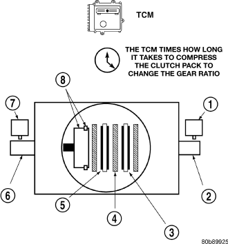
Gear ratios can be determined by using the DRBIII® Scan Tool and reading the Input/Output Speed Sensor values in the “Monitors” display. Gear ratio can be obtained by dividing the Input Speed Sensor value by the Output Speed Sensor value.
The gear ratio changes as clutches are applied and released. By monitoring the length of time it takes for the gear ratio to change following a shift request, the TCM can determine the volume of fluid used to apply or release a friction element.
The volume of transmission fluid needed to apply the friction elements are continuously updated for adaptive controls. As friction material wears, the volume of fluid need to apply the element increases.
Certain mechanical failures within the input clutch assembly can cause inadequate or out-of-range element volumes. Also, defective Input/Output Speed Sensors and wiring can cause these conditions. The following chart identifies the appropriate clutch volumes and when they are monitored/updated:
| CLUTCH VOLUMES |
||
| Clutch |
When Updated |
Proper Clutch Volume |
| L/R |
2-1 or 3-1 downshift |
45 to 134 |
| 2C |
3-2 kickdown shift |
25 to 85 |
| OD |
2-3 upshift |
30 to 100 |
| 4C |
3-4 upshift |
30 to 85 |
| UD |
4-3 kickdown shift |
25 to 100 |
SHIFT SCHEDULES
As mentioned earlier, the TCM has programming that allows it to select a variety of shift schedules. Shift schedule selection is dependent on the following:
- Shift lever position
- Throttle position
- Engine load
- Fluid temperature
- Software level
As driving conditions change, the TCM appropriately adjusts the shift schedule. Refer to the following chart to determine the appropriate operation expected, depending on driving conditions.
| Schedule |
Condition |
Expected Operation |
| Extreme Cold |
Oil temperature below -27° C (16° F) |
-Park, Reverse, Neutral and 1st and 3rd gear only in D position, 2nd gear only in Manual 2 or L |
| -No EMCC |
||
| Super Cold |
Oil temperature between -24° C (-12° F) and -12° C (10° F) |
- Delayed 2-3 upshift |
| - Delayed 3-4 upshift |
||
| - Early 4-3 coastdown shift |
||
| - High speed 4-2, 3-2, 2-1 kickdown shifts are prevented |
||
| -Shifts at high throttle openings willl be early. |
||
| - No EMCC |
||
| Cold |
Oil temperature between -12° C (10° F) and 2° C (36° F) |
-Shift schedule is the same as Super Cold except that the 2-3 upshifts are not delayed. |
| Warm |
Oil temperature between 4° C (40° F) and 27° C (80° F) |
- Normal operation (upshift, kickdowns, and coastdowns) |
| - No EMCC |
||
| Oil temperature between 27° C (80° F) and 115° C (240° F) |
- Normal operation (upshift, kickdowns, and coastdowns) |
|
| Hot |
- Normal EMCC operation |
|
| Overheat |
Oil temperature above 115° C (240° F) or engine coolant temperature above 118° C (244° F) |
- Delayed 2-3 upshift |
| - Delayed 3-4 upshift |
||
| - 3rd gear FEMCC from 30-48 mph |
||
| - 3rd gear PEMCC above 35 mph |
||
| - Above 25 mph the torque converter will not unlock unless the throttle is closed or if a wide open throttle 2nd PEMCC to 1 kickdown is made |