SEAL-PINION
REMOVAL
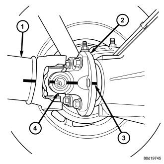
1. With vehicle in neutral, position vehicle on hoist.
2. Mark a reference line across the companion flange (3) and propeller shaft flange (4).
3. Remove propeller shaft
4. Remove brake calipers and rotors to prevent any drag.
5. Rotate flange three or four times and verify flange rotates smoothly.
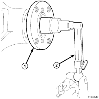
6. Measure torque to rotating pinion with a inch pound torque wrench (2). Record reading for installation reference.
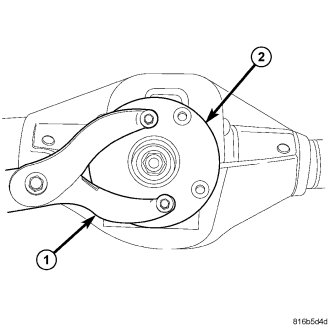
7. Hold companion flange (2) with Wrench C-3281 (1) and remove pinion nut.
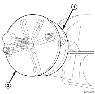
8. Remove companion flange (1) with Remover 8992 (2).
9. Remove pinion seal with a seal puller.
INSTALLATION
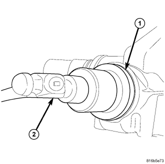
1. Apply a light coating of gear lubricant on the lip of pinion seal.
2. Install new pinion seal with Installer 8889 (1) and hammer (2).
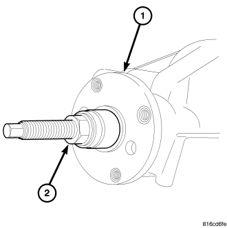
3. Install flange on pinion shaft with the reference marks aligned.
4. Install companion flange (1) with Installer C-3718 (2).
5. Install pinion a new pinion nut.
CAUTION: Do not exceed the minimum tightening torque when installing the companion flange retaining nut at this point. Failure to follow these instructions can damage the collapsible spacer or bearings.
6. Hold companion flange (2) with Wrench C-3281 (1) and tighten pinion nut to 298 N·m (220 ft. lbs.). Rotate pinion several revolutions to ensure bearing rollers are seated.
7. Set torque wrench to 678 N·m (500 ft. lbs.) and tighten pinion nut in 6.8 N·m (5 ft. lbs.) increment until Pinion Torque To Rotate specification is achieved.
8. Measure pinion torque to rotate with an inch pound torque wrench (2). Torque To Rotating should be equal to the reading recorded during removal plus an additional 0.56 N·m (5 in. lbs.).
CAUTION: Never loosen pinion nut to decrease pinion bearing rotating torque and never exceed specified preload torque. If rotating torque is exceeded, a new collapsible spacer must be installed. Failure to follow these instructions can damage the collapsible spacer or bearings.
9. If torque to rotating is low, tighten pinion nut in 6.8 N·m (5 ft. lbs.) increments until proper rotating torque is achieved.
NOTE: The bearing rotating torque should be constant during a complete revolution of the pinion. If the rotating torque varies, this indicates a binding condition.
10. Install propeller shaft.
11. Install rear brake components.