SEAT TRACK POSITION SENSOR
DESCRIPTION
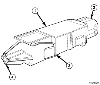
The seat track position sensor (1) is a Hall Effect-type sensor. This sensor consists of a Hall Effect Integrated Circuit (IC) chip encased in potting material within a cavity of the molded plastic sensor housing.
The sensor housing has an integral snap feature (3) and snaps into a stamped metal bracket located on the inboard side of one of the seat adjuster tracks on the passenger side front seat, then is secured by a screw into a mounting boss (4) at one end of the sensor housing. A molded connector receptacle (2) that is integral to the opposite end of the sensor housing from the mounting boss is connected to the vehicle electrical system through a connector and take out of the passenger seat wire harness beneath the front seat cushion frame.
The seat track position sensor cannot be adjusted or repaired and, if ineffective or damaged, the entire sensor must be replaced.
OPERATION
The seat track position sensor is designed to provide a seat position data input to the Occupant Restraint Controller (ORC) indicating whether the passenger side front seat is in a full forward or a not full forward position. The ORC uses this data as an additional logic input for use in determining the appropriate deployment force to be used when deploying the multistage passenger side front airbag.
The seat track position sensor receives a nominal five volt supply from the ORC. The sensor communicates the seat position by modulating the voltage returned to the ORC on a sensor data circuit. The ORC also monitors the condition of the sensor circuits and will store a Diagnostic Trouble Code (DTC) for any fault that is detected, then sends a message to illuminate the airbag indicator in the ElectroMechanical Instrument Cluster (EMIC) (also known as the Cab Compartment Node/CCN).
The hard wired circuits between the seat track position sensor and the ORC may be diagnosed using conventional diagnostic tools and procedures. Refer to the appropriate wiring information. However, conventional diagnostic methods will not prove conclusive in the diagnosis of the seat track position sensor or the electronic controls and communication between other modules and devices that provide features of the supplemental restraint system. The most reliable, efficient, and accurate means to diagnose the seat track position sensor or the electronic controls and communication related to seat track position sensor operation requires the use of a diagnostic scan tool. Refer to the appropriate diagnostic information.
REMOVAL
WARNING: To avoid personal injury or death, on vehicles equipped with airbags, disable the supplemental restraint system before attempting any steering wheel, steering column, airbag, seat belt tensioner, impact sensor, or instrument panel component diagnosis or service. Disconnect and isolate the battery negative (ground) cable, then wait two minutes for the system capacitor to discharge before performing further diagnosis or service. This is the only sure way to disable the supplemental restraint system. Failure to take the proper precautions could result in accidental airbag deployment.
1. Disconnect and isolate the battery negative cable. Wait two minutes for the system capacitor to discharge before further service.
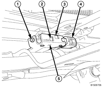
2. Reach under the front seat cushion to access the seat track position sensor (3) in a bracket (5) located on the inboard side of either the inner or outer, driver or passenger seat track.
3. Disconnect the seat wire harness connector (4) from the sensor.
4. Remove the screw (1) that secures the sensor mounting boss to the bracket.
5. Using a small screwdriver, depress the sensor latch feature (2) and pull the sensor out of the bracket.
INSTALLATION
WARNING: To avoid personal injury or death, on vehicles equipped with airbags, disable the supplemental restraint system before attempting any steering wheel, steering column, airbag, seat belt tensioner, impact sensor, or instrument panel component diagnosis or service. Disconnect and isolate the battery negative (ground) cable, then wait two minutes for the system capacitor to discharge before performing further diagnosis or service. This is the only sure way to disable the supplemental restraint system. Failure to take the proper precautions could result in accidental airbag deployment.
1. Reach under the front seat cushion to position the seat track position sensor (3) to the open end of the bracket (5) located on the inboard side of either the inner or outer, driver or passenger seat track.
2. Push the sensor firmly into the bracket until the latch feature (2) snaps into place.
3. Install and tighten the screw (1) that secures the sensor mounting boss to the bracket. Tighten the screw to 2 N·m (15 in. lbs.).
4. Reconnect the seat wire harness connector (4) to the sensor connector receptacle located on the end of the sensor. Be certain that the latch on the connector is fully engaged.
5. Do not reconnect the battery negative cable at this time. The supplemental restraint system verification test procedure should be performed following service of any supplemental restraint system component. (Refer to 8 - ELECTRICAL/RESTRAINTS - STANDARD PROCEDURE - VERIFICATION TEST).