INSTALLATION
FRONT
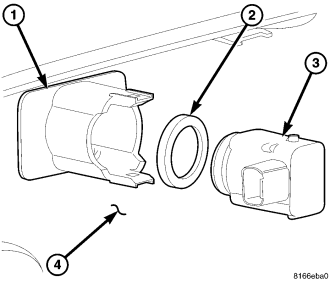
NOTE: The park assist sensors (3) and the sensor spacers (2) are each available for separate service replacement. The sensor brackets (1) are bonded and integral to the back side of the front bumper fascia (4).
1. Engage the O-ring spacer (2) around the circumference of the sensor (3) membrane protrusion.
NOTE: Production and all service replacement O-ring spacers are tapered. The wide side (base) of the O-ring should be seated against the sensor housing and the narrow side should be oriented toward the outer surface of the sensor membrane and the front fascia.
2. Align and insert the sensor into the sensor bracket (1) on the back of the front bumper fascia (4) until the bracket latch features are fully engaged over the top and bottom tabs of the sensor. Be certain that the sensor membrane is flush with the outer surface of the fascia.
NOTE: Be certain that each sensor membrane is properly centered in the openings of the front fascia and that the O-ring spacers are not pinched. Improper centering or pinched O-rings can be detrimental to proper park assist sensor operation.
3. From the back of the fascia, reconnect the wire harness connector to the sensor connector receptacle.
4. Reinstall the bumper fascia onto the front of the vehicle. (Refer to 13 - FRAME AND BUMPERS/BUMPERS/FRONT FASCIA - INSTALLATION).
5. Reconnect the battery negative cable.
REAR
NOTE: The park assist sensors, the sensor O-ring spacers and the sensor brackets are each available for separate service replacement. The following service procedure can be used for reassembling any or all of these components to the rear bumper fascia.
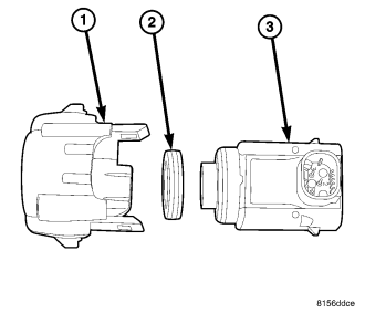
1. If the park assist sensor (3) or the sensor spacer (2) are being replaced, engage the O-ring spacer around the circumference of the sensor membrane protrusion.
NOTE: Production and all service replacement O-ring spacers are tapered. The wide side (base) of the O-ring should be seated against the sensor housing and the narrow side should be oriented toward the outer surface of the sensor membrane and the rear fascia molding.
2. If the sensor bracket (1) is being replaced, align and insert the sensor into the sensor bracket until the bracket latch features are fully engaged over the top and bottom tabs of the sensor. Be certain that the sensor spacer is in place around the circumference of the sensor membrane protrusion.
3. If the sensor bracket is being replaced, align and insert the bracket and sensor unit between the fascia molding latch features until the top and bottom tabs of the sensor bracket are fully engaged. Be certain that the sensor membrane is flush with the outer surface of the fascia molding.
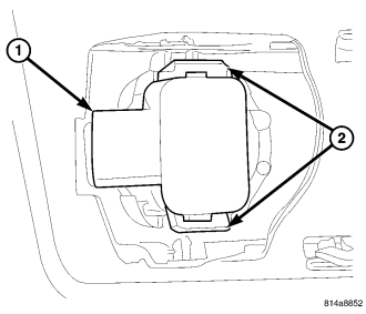
4. If only the sensor or the sensor spacer are being replaced, align and insert the sensor into the sensor bracket on the back of the rear bumper fascia until the bracket latch features (2) are fully engaged over the top and bottom tabs of the sensor. Be certain that the sensor membrane is flush with the outer surface of the fascia molding.
NOTE: Be certain that each sensor membrane is properly centered in the openings of the rear fascia molding and that the O-ring spacers are not pinched. Improper centering or pinched O-rings can be detrimental to proper park assist sensor operation.
5. From the back of the fascia, reconnect the wire harness connector to the sensor connector receptacle (1).
6. Reinstall the bumper fascia onto the rear of the vehicle. (Refer to 13 - FRAME AND BUMPERS/BUMPERS/REAR FASCIA - INSTALLATION).
7. Reconnect the battery negative cable.