SENSOR
DESCRIPTION
NOTE: On vehicles equipped with a Tire Pressure Monitoring System (TPMS), when the spare tire pressure sensor is replaced with a new pressure sensor, a diagnostic scan tool MUST be used to run a routine that will program the new pressure sensor ID into the Wireless Control Module (WCM), commonly referred to as the Sentry Key Remote Entry Module (SKREEM). Please copy the ID number off of the new pressure sensor before installing it into the spare tire. Then follow the programming steps outlined in the diagnostic scan tool for: “Learn Spare Tire Sensor ID” under” Miscellaneous Functions” for the “WCM/Wireless Control Module” menu item as appropriate. Then install the spare tire with one of the active road tires.
NOTE: If replacing the WCM, the spare tire must be dismounted from its wheel to access and note the spare tire pressure sensor ID. Then follow the programming steps outlined in the diagnostic scan tool for “Learn Spare Tire Sensor ID” under “Miscellaneous Functions” for the “WCM/Wireless Control Module”? menu item as appropriate. In addition, the placard pressure thresholds must be updated in the new WCM. Go to "Update Pressure Thresholds" under "Miscellaneous Functions" for the "WCM Wireless Control Module" and follow the procedure.
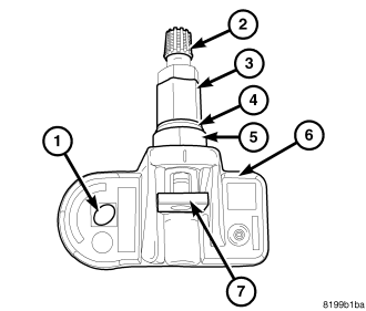
On vehicles equipped with Tire Pressure Monitoring System, one tire pressure sensor (6) is mounted to each wheel in place of the traditional tire valve stem. Each sensor has an internal battery that lasts up to 10 years. The battery is not serviceable. At the time of battery failure, the sensor must be replaced.
The TPM system operates on a 315 MHz radio frequency. The 315 MHz sensors can be easily identified by a black sensor body, with (an oval insignia) (1) and a grey valve cap (2).
The Export TPM system operates on a 433 MHz radio frequency. The 433 MHz sensors can be easily identified by a gray sensor body (with a oval insignia) and a black valve cap (2).
CAUTION: Although 315 MHz and 433 MHz sensors are identical in size and shape, they are not interchangeable. Always make sure the correct sensor is being used.
NOTE: Sensors may be identified by valve stem cap color. From the factory, 315 MHz sensors have a gray valve stem cap while 433 MHz sensors have a black valve stem cap. Otherwise, once mounted inside a tire and wheel assembly you are not able to visually tell the difference between a 315 MHz and 433 MHz sensor. The tire must be dismounted allowing visual inspection of the sensor body.
NOTE: If aftermarket wheels are installed and do not contain tire pressure sensors, the system will not function properly and the driver will be continuously notified of a system malfunction.
The TPM sensors are designed for original style factory wheels. It is not recommended to install a tire pressure sensor in an aftermarket wheel. (This could cause sealing and system performance issues).
The serviceable components of the tire pressure sensor are:
NOTE: Any time a sensor is installed on a wheel, a new Sensor-To-Wheel Seal (4) must be installed to ensure proper sealing.
- Sensor-To-Wheel Seal (4)
- Valve Stem Cap (2)
- Valve Stem Core
- Valve Stem Nut (3)
The valve stem caps and cores used are specifically designed for the tire pressure monitoring sensors. Although similar to standard valve stem caps and cores, they are different. The valve stem cap has a special seal inside to keep moisture and corrosion out. The valve stem core has a special nickel coating to protect from corrosion.
OPERATION
NOTE: On vehicles equipped with a Tire Pressure Monitoring System (TPMS), when the spare tire pressure sensor is replaced with a new pressure sensor, a diagnostic scan tool MUST be used to run a routine that will program the new pressure sensor ID into the Wireless Control Module (WCM), commonly referred to as the Sentry Key Remote Entry Module (SKREEM). Please copy the ID number off of the new pressure sensor before installing it into the spare tire. Then follow the programming steps outlined in the diagnostic scan tool for: “Learn Spare Tire Sensor ID” under” Miscellaneous Functions” for the “WCM/Wireless Control Module” menu item as appropriate. Then install the spare tire with one of the active road tires.
NOTE: If replacing the WCM, the spare tire must be dismounted from its wheel to access and note the spare tire pressure sensor ID. Then follow the programming steps outlined in the diagnostic scan tool for “Learn Spare Tire Sensor ID” under “Miscellaneous Functions” for the “WCM/Wireless Control Module”? menu item as appropriate. In addition, the placard pressure thresholds must be updated in the new WCM. Go to "Update Pressure Thresholds" under "Miscellaneous Functions" for the "WCM Wireless Control Module" and follow the procedure.
The battery operated tire pressure sensor is both a transmitter and a receiver. The TPM sensor can be forced to transmit if using a special tool such as a TPM-RKE Analyzer, or from a transponder. (Refer to 22 – TIRES/WHEELS/TIRE PRESSURE MONITORING/TRANSPONDER - OPERATION) The TPM-RKE Analyzer has the ability to change the sensor’s operating mode and to diagnose a faulty TPM sensor. Using a TPM-RKE Analyzer can take up to a minute to force a transmission from a sensor. The TPM sensor can be in one of the following modes:
- • Sleep Mode – This is the operating mode of a new TPM sensor. If placed on the vehicle as a road tire, the sensor will transmit once every 20 seconds when the vehicle is driven at speeds over 15 mph (24 km/h). If the vehicle is not moving, the sensor will only transmit on a pressure change greater then 1 PSI. Driving the vehicle continuously at this speed for more then 4 minutes, and then stopping the vehicle will change the sensor state into Park Mode. If the vehicle is equipped with a full size matching spare tire and the spare tire sensor has been replaced, The sensor must be changed to Park Mode to conserve battery life. Either use a TPM-RKE Analyzer, or swap the spare tire with a road tire.
- • Park Mode – This is the correct operating mode when the vehicle is not moving. The sensor will transmit once every 13 hours to update the WCM, or will transmit on a 1 PSI delta change. The sensors will internally take a measurement of the tire pressure every minute to determine a change in tire pressure
- • 0ff / 30 Block – If the vehicle has been stopped for more then 20 minutes, or if the sensor’s operating mode was forced to Park Mode using a TPM-RKE Analyzer, the sensor’s operating mode will transition from Park Mode to 30 Block Mode once the vehicle is driven over 15mph. In this mode, the sensor will transmit once every 15 seconds when the vehicle is driven at speeds over 15 mph (24 km/h) for the first 30 transmissions. After about 8 minutes of continuous driving above 15 mph (24 km/h), the sensor’s mode will change to Drive Mode
- • Drive Mode – In this mode, the sensor will transmit once every minute when the vehicle is driven at speeds over 15 mph (24 km/h). At any time the vehicle speed drops below 15mph, the sensor will revert back to Park Mode. The sensor mode will still be in drive mode when the sensor reaches speeds over 15 mph (24 km/h), unless the vehicle has been stationary for more then 20 minutes.
Each sensor’s (transmitter) broadcast is uniquely coded so that the wireless control module (WCM) can monitor the state of each of the sensors on the four rotating road wheels. The WCM can automatically learn and store the sensor’s ID while driving “within 10 minutes continuously above 15 m.p.h. (24 Km/h)” after a sensor has been replaced, The vehicle must be stationary for more then 20 minutes in order to initiate the learning sequence.
CAUTION
CAUTION: The use of tire sealants is not recommended for vehicles equipped with the Tire Pressure Monitoring system. Tire sealants may clog tire pressure sensors.
CAUTION: Tire pressure sensor valve stem caps and cores are specially designed for the sensors. Due to risk of corrosion, do not use a standard valve stem cap or core in a tire pressure sensor in place of the original equipment style sensor cap and core.
CAUTION: It is not recommended to install a tire pressure sensor in an aftermarket wheel. Use tire pressure sensors in original style factory wheels only.
CAUTION: Any time a sensor is to be reinstalled in a wheel, a new seal, cap and valve core must be installed on the stem to ensure air tight sealing.
NOTE: TPM thresholds have been established for the original tire size equipped on the vehicle. Use original size tires only to maintain system accuracy.
REMOVAL
1. Raise and support vehicle. (Refer to LUBRICATION & MAINTENANCE/HOISTING - STANDARD PROCEDURE)
2. Remove the tire and wheel assembly (Refer to 22 - TIRES/WHEELS/WHEELS - STANDARD PROCEDURE).
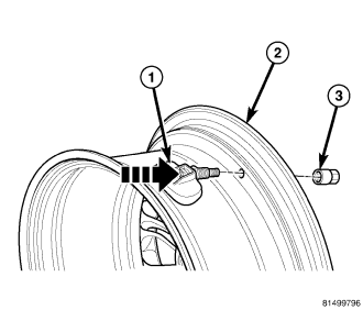
CAUTION: The cap used on this valve stem contains an O-ring seal to prevent contamination and moisture from entering the valve stem. Retain this valve stem cap for reuse. Do not substitute a regular valve stem cap in its place.
CAUTION: The valve stem used on this vehicle is made of aluminum and the core is nickel plated brass. The original valve stem core must be reinstalled and not substituted with a valve stem core made of a different material. This is required to prevent corrosion in the valve stem caused by the different metals.
3. Let the air out of the tire.
4. Remove the nut (3).
5. Push the sensor into the tire (1) ( so the sensor is loose inside the tire).
6. Remove the tire from the rim.
7. Retrieve the sensor (1) from the tire.
INSTALLATION
NOTE: If replacing the spare tire pressure sensor, take the time now to write down the tire pressure sensor ID.
NOTE: Before reinstalling an existing tire pressure sensor (6), replace valve cap (2), valve core and sensor seal (4) to ensure proper sealing.
NOTE: The notch/flat should be lined up together and facing towards the wheel during installation.
1. Wipe area clean around sensor/valve stem mounting hole in wheel. Make sure surface of wheel is not damaged.
2. Insert sensor (1) through wheel (2) as shown keeping pressure against rear of metal valve stem (See Arrow). Potted side of sensor is to be positioned toward wheel. Damage to the sensor may occur if the sensor is installed incorrectly.
NOTE: A flat on the seal seat is used to key the seat to the sensor housing. The notch/flat should be lined up together and facing towards the wheel during installation.
3. Install sensor nut (3) and hand tighten.
NOTE: Before tightening sensor nut, push downward on sensor housing (2) in an attempt to make it flush with interior contour of wheel (1).
4. While holding sensor in position, tighten sensor nut to 8 N·m (71 in. lbs.) torque.
CAUTION: Over-torquing the sensor to as much as 10 N·m (88 in. lbs.) may result in sensor separation from the valve stem. Under this condition, the sensor may still function, however, the condition should be corrected immediately.
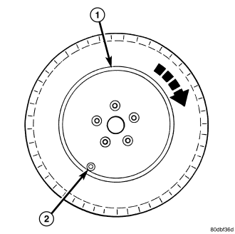
5. Mount tire on wheel following tire changer manufacturers instructions, paying special attention to the following to avoid damaging tire pressure sensor:
a.
b.
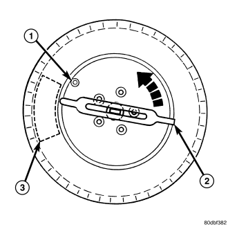
6. Adjust air pressure to that listed on Tire Inflation Pressure Label (Placard) provided with vehicle (usually applied to driver's side B-pillar). Make sure original style valve stem cap is securely installed to keep moisture out of sensor.
7. Install tire and wheel assembly on vehicle (Refer to 22 - TIRES/WHEELS/WHEELS - STANDARD PROCEDURE).
8. Lower vehicle.
9. If the vehicle has been stationary for more then 20 minutes, drive the vehicle for a minimum of 10 minutes while maintaining a continuous speed above 15 mph (24 km/h). During this time, the system will learn the new sensor ID.
NOTE: If a sensor cannot be trained, refer to appropriate diagnostic information.
SPARE TIRE SENSOR REPLACEMENT
NOTE: When the spare tire sensor is replaced on vehicles equipped with a Tire Pressure Monitoring System (TPMS) and a full-sized matching spare tire and wheel assembly, a diagnostic scan tool MUST be used to run a routine that will program the new pressure sensor ID into the Wireless Control Module (WCM), commonly referred to as the Sentry Key Remote Entry Module (SKREEM). Please copy the ID number off of the new pressure sensor before installing it into the spare tire. Then follow the programming steps outlined in the diagnostic scan tool for: “Learn Spare Tire Sensor ID” under” Miscellaneous Functions” for the “WCM/Wireless Control Module” menu item as appropriate. If a TPM-RKE Analyzer special tool is available, put the new spare tire pressure sensor into “Park” mode. If a TPM-RKE Analyzer special tool is not available, rotate the spare tire with one of the road tires.