ASSEMBLY-SHIFT MOTOR/MODE SENSOR
DESCRIPTION
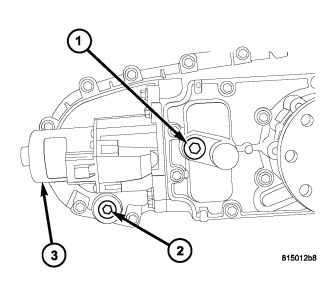
The shift motor (3) is an electromechanical device consisting of a DC permanent magnet motor, a gear train, an analog position sensor, and a position holding brake. The shift motors' overall function is to move and lock a gear that moves the range fork and clutch lever found in the transfer case. This allows the transfer case to be shifted electrically to multiple operating positions (4LOW and AWD). The operating current of the shift motor under stall conditions is 30 amps maximum at 72° F with 13.5 volts, at the motor leads.
OPERATION
Shifting in the transfer case occurs when a Pulse Width Modulated (PWM) voltage is supplied to the shift motor by the Final Drive Control Module (FDCM). A linear analog position sensor located inside the shift motor, provides the FDCM with the motors' angular, rotational position. With this information, the FDCM continuously knows the motors' position, and therefore allows it to accurately control the motors' operation, including voltage polarity which is used to control motor direction.
REMOVAL
NOTE: New shift motor assemblies are shipped in the NEUTRAL position. If a new shift motor assembly must be installed, it will be necessary to shift the transfer case to the NEUTRAL position prior to motor installation.
1. Raise the vehicle on a suitable hoist.
2. Disengage the wiring connector from the shift motor and mode sensor assembly.
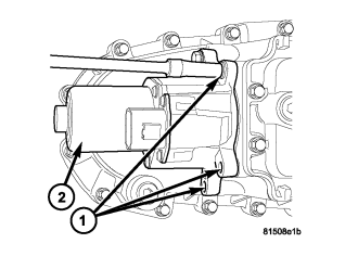
3. Remove the bolts (1) holding the shift motor and mode sensor assembly (2) onto the transfer case.
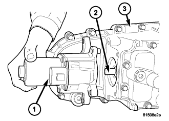
4. Separate the shift motor and mode sensor assembly (1) from the transfer case (3) and shift sector (2).
INSTALLATION
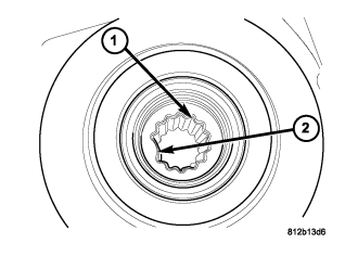
1. Verify that the shift motor o-ring is clean and properly positioned inside the machined o-ring groove of the shift motor.
NOTE: Verify that the missing tooth (2) in the shift motor drive spline (1)...
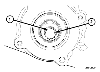
NOTE: ...and the transfer case drive spline (1) missing tooth (2) are aligned. It may be necessary to manually shift the transfer case if the shift motor and transfer case shaft are not aligned.
2. Position the shift motor and mode sensor assembly (1) onto the transfer case (3) and shift sector (2).
3. Install the bolts (1) to hold the assembly (2) onto the transfer case. Tighten the bolts to 25-28 N·m (18.5-20.5 ft.lbs.).
CAUTION: If the original shift motor and mode sensor assembly bolts are reused, be sure to use Mopar® Lock & Seal or Loctite™ 242 to replenish the lock patch material originally found on the bolts
4. Engage the wiring connector to the shift motor and mode sensor assembly.
5. Lower vehicle and verify transfer case operation.